Sunday, December 11, 2016

DVMEGA Raspberry Pi DMR with TYT-380

This is going to be one of those posts that if you don't know much about the subject...you won't know much more at the end.

Long story as short as I can...

The lastest technology available to Amateur Radio hobbyists is digital audio.   So same radio frequencies, but instead of analog audio like on your old walkie talkie...it is digital audio like your cellphone/skype/etc.  Why? More conversations on a frequency, better audio, 'caller id, internet connectivity. etc

So I picked up a cheap DMR HT the TYT-380 I wrote about before.   It works great, DMR programming is complicated due to the capabilities of DMR.


Unfortunately my house is a Faraday cage, and signals have a hard time making it through the walls...so I can only use the radio outside the house.

A technology that has been available for a while and are really maturing are Digital Voice hotspots.   This took me a while to understand the usefulness...because the job it did wasn't really well described.  I have a DV hotspot that has a small radio and connects to the internet...my radio can talk to this hotspot which puts my radio on the internet...most Repeater or other hotspots are ALSO on the internet...so this hotspot is my connection to the larger radio world.   This hotspot lets me use my DMR radio inside the house.

There are a lot of choices of  'gateway' or 'hotspot' depending on need and what digital radio technology you are using (DMR, DSTAR, FUSION, for a few examples)

So again the problem is I cannot use my DMR in the house.   The solution I chose is the DVMEGA board mounted on a Raspberry Pi.  There are other types...this is simply the one I chose.


I am not going to regurgitate all the well documented steps, I am simply going to list the links I used, and the problems I encountered...in all cases I made an error/didn't fully understand.

You will need the DVMEGA board...I got the dual band version(from Gigaparts) or. http://dvmega.auria.nl/
You need a Raspberry Pi...I have version 3s.
You need an antenna for the DVMEGA board (unless it comes with yours)  I am using a stubby rubber ducky style antenna.

One thing they don't tell you is the DVMEGA is a self contained Arduino powered board...so there will be firmware updates for it...unless you have some kind of special serial programmer (available separately) you will need another method to do the updates...and it involves soldering.   If you do not want to solder, then I would look at a different solution for your DV hotspot.

http://www.dvmega.auria.nl/Downloads.html

https://g0wfv.wordpress.com/how-to-update-dvmega-firmware-without-a-programmer-or-an-arduino/

https://www.florian-wolters.de/blog/2016/03/12/firmware-upgrade-on-dvmega-without-programmer/

So my first problem involved the soldering...I did it in my office (I don't have a magnifying glass here, and you are soldering on a SMD component) and apparently I didn't get a good connection...it took about a day of battle to troubleshoot that one.

https://www.florian-wolters.de/blog/2016/03/12/firmware-upgrade-on-dvmega-without-programmer/#imgModal-89

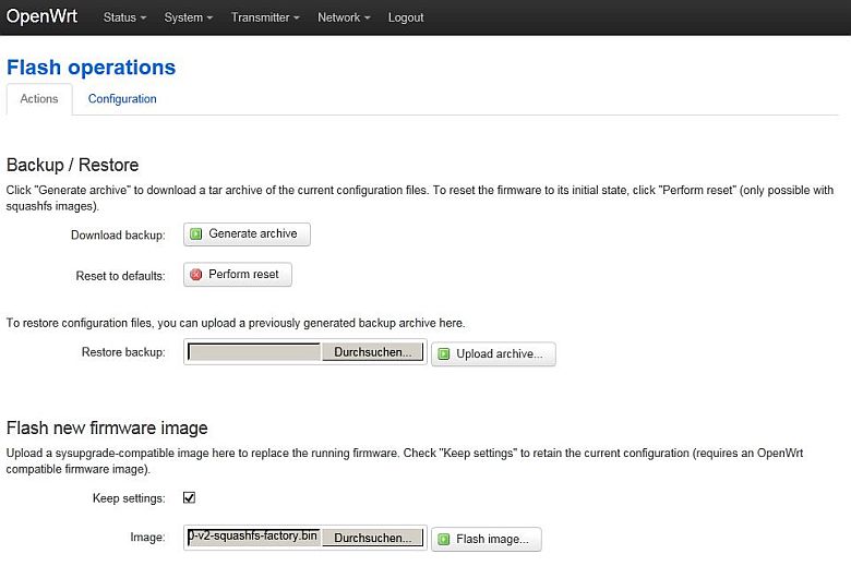
Once the firmware successfully updated, it was all pretty much straight forward.  The second part was getting the software that does the DV stuff onto the Raspberry Pi.  The two ways to do it are to use a standard RPi install and add the new software, or download an already created image...well I did both and downloaded 5 RPi images in the process...that took forever.

BTW the software that does the DMR (and others) is MMDVMHost

For the image, the last one I found (by accident...well hidden) is from DMR-UTAH   http://www.dmr-utah.net/support/mmdvm/images/

I recommend going straight to that one.  You still have to edit a file...but there is a shortcut to all the tools.

https://wiki.brandmeister.network/index.php/DVMEGA

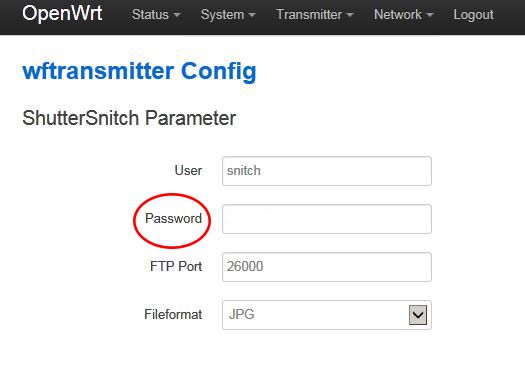
The BrandMeister link has the best explanation for the settings...a VERY IMPORTANT SETTING IS Port=/dev/ttyAMA0   There are a variety of other ones in the settings...but this is the only one you want.

https://www.hamdigitaal.nl/?p=6122 (one of my attempts used a DSTAR Pi image)

So assuming the firmware update went well, and you are running the software on the Pi...how do you know if it is working...this also took a while for me to track down, but found simple solutions for that.

First, with the software running on the Pi, when I transmit with my radio, the Terminal window running on the Pi will show the transmission and my callsign...and if it is receiving data it will show those callsigns.   But what do I sound like...is anyone trying to call me?   Found an easy tester for that.

BrandMeister is the voluntary collective for DV through internet...they have some good info (not all, but some)  They also have a couple of good tools.   LastHeard shows all the current connections world wide...you can filter the results to your callsign.  Second one is Hoseline , you select a TalkGroup number (note I typed in 3100 in the URL) and it will play the live audio...so select the TalkGroup you will be transmitting on, and when you transmit, your audio will come from the webpage.  BTW between all the various moving parts...the audio I heard on the website of other transmission I also heard simultaneously on my HT through the DVMEGA-Pi.

Those two tools really gave me a warm fuzzy that everything on my end was working properly, and the final confirmation was a very positive signal report from an Amateur radio operator who was south of Milan Italy.

The last hard part about this setup is programming the radio...essentially your hotspot is a repeater, so add it to your radio settings like you would add any other DMR repeater.

Some TalkGroups.

http://www.trbo.org/talkgroups/

https://wiki.brandmeister.network/index.php/United_States_of_America


Friday, December 9, 2016

Laserdisc audio/video setup

Ok, so I have issues.   I enjoy the act of playing vinyl records...I like the fact they are fragile and require care and a bit of effort to play music.   It is part of the charm.

So in ancient times (late 80's) I was in a video store (remember those) and watched the U2 Live at Red Rocks: Under a Blood Red Sky concert playing on a laserdisc.   I was amazed at the picture and the sound (VHS was all you had then).   Some video stores had LaserDiscs to rent, but the machines were VERY expensive (twice what a VHS machine cost) and only played, no recording.   To buy a movie on laserdisc was another expensive proposition.  (first released around 1984)

(price $1200 in 1995, new)

Well since I didn't have any money, I didn't invest in that technology...but I remember lusting after it.

Fast forward to last year, I am watching some YouTube videos from a couple of different channels about old audio and video formats...and saw that there is still strong support for the laserdisc players and the discs themselves.   The format died around 2000, so there are no new disks past that point...and no new players after 2009.

Techmoan YouTube Channel

Culturedog YouTube Channel


For whatever reason, I decided that I wanted to join this hobby...there is no good reason to do so, but it seemed to make sense at the time...sort of like vinyl...there is an effort involved in watching a movie on laserdisc.


Some interesting things about the LD format...the video was pulled live directly from the films...live as in they would run a batch through to record it electronically, then check the quality...if they didn't like it they would change some settings and run it through again.   In most cases they had representatives of the move (directors etc) to evaluate the copy and approve or disapprove...in some cases it took 5 tries to get the copy they wanted.   So a LD is a permanent copy of a film the last time it was shown...film imperfections and all.   For me, it is like being back in the theater.

Audio is another subject.  There are 4 types of audio available depending on the disc...and again, for the most part it is whatever the movie had.  All audio is recorded as a kind of radio signal on the disc (you can research that yourself).  Your choices are plain old Stereo Analog.  Digital Stereo, AC-3 digital surround, DTS digital surround.


(BTW, to my ear the LD Digital audio is amazing...I am not a audiophile with $1000 speaker wires, but it sounds fuller and I hear details that I never noticed on DVD or BD of the same move)

Analog is those two plugs you stick in the back of the stereo.   Audio quality is as good as the converter on the player.
Digital Stereo is a digital conversion direct from the RF feed...so it is as good as your decoder (receiver) is.
AC-3 digital surround was a way to get the full 5.1 surround data to a decoder...right now almost no receivers have AC-3 decoders...so you need an additional decoder.
DTS digital surround was the other way to get full 5.1 surround data...most good receivers have DTS decoders built in...no additional decoder required.

Every disc has the Analog data on it.   Most have Digital Stereo outputs.   Quite a few newer releases have AC-3 versions available...but the packaging was similar to the Digital Stereo ones...so you have to look carefully...if there is an AC-3 version, then there is also a Digital Stereo only version.  DTS is very rare...I only have a couple myself...it was limited production, and only a few movies were released with it.


(use the LDDB.com to figure out what version is what)

The better than average LD players had the Digital outputs...so you can play DTS on most of them...only a few LD players had the AC-3 output...So it is hard to get DTS movies, easy to get players...hard to get AC-3 players, easy to get movies.


I ended up with the Pioneer CLD-D704 which is at the top end of the (now) affordable LD players...there are some sold in Japan at about 5 times the price that are better...if you can find them.   The CLD-D704 has the AC-3 output and arguably some of the best video playback.

Oh, about that.   All playback is composite.   The laserdiscs were encoded as composite video data...that means your S-Video plug doesn't improve anything.  The video output is comparable to DVD.

So what do you do with that in an HD world?   You buy more parts.  To sum it up...the composite output has issues, and up-scaling to HD makes more issues.   Many receivers can do it (mine included) but with varying degrees of quality.   Mine is tolerable...but not good.

So in following the forums I learned that the best machine for cleaning up the composite video signal (comb filter) is a DVD recorder (say what?)  So I got a Panasonic DMR-ES10 off ebay with a broken remote sensor that I was able to fix for cheap.


I have the composite video and analog audio going into the ES-10 from the LD.   Now to upscale it, I got a DVDO iScan HD+ which can up-scale to 1080P.  I send COMPONENT out from the ES-10 to the DVDO.   Yes, the ES-10 separates the composite input to component.

It only has DVI outputs, so I had to get a DVI to HDMI adapter to plug into my receiver.   Also the up-scaling creates a bit of delay, so I put the Digital Optical through this then to the receiver...it won't send audio over DVI.

Now for the audio...I need the ability to decode AC-3...but if no AC-3 then I need to send Digital Stereo/DTS ...and I don't want to have to switch audio inputs all the time.   So I got the Denon AVD-2000.


I have the AC-3 and Digital out plugged into this thing, and if there is AC-3 it automatically selects it...otherwise just the Digital Optical, and it sends that to the DVDO.   However some LDs have only Analog audio...so I put the Analog audio into the ES10, and plug the digital out from that into the AVD-2000...that way if I have to switch to Analog, I only have to hit one button, AND because I am sending the Analog though the same path as the digital, any delays in up-scaling will be synced.

So does it work...well whenever someone puts this much effort into a setup, they will of course say it looks great.   Well, the way I have everything hooked up, I had to select a lot of different inputs to make sure I had everything wired correctly...the LD player has two composite outputs, the ES-10 can output composite and component.   the DVDO can accept all sorts of inputs.   So I had one composite directly from the LD to the DVDO, one from the ES-10 to the DVDO and a component set from the ES-10 to the DVDO.

First test was LD and DVDO composite only.   Scaling was nice, no artifacts, but color seemed a bit washed out...I played with the DVDO settings but couldn't make much change.

Second was LD to ES-10 to DVDO using composite.   Everything else was the same but color looked a bit better, maybe still a bit washed out.

Third was LD to ES-10 to DVDO using component.   WOW that changed everything!   Color was good, but black level and contrast were amazing...

Now, my test disk was Pink Floyd live at Pompeii...a 70's concert movie...which already had some artifacts due to the film quality...but it looked good to me.


Here is how it is all wired up...fun huh.   (of course there are about a half dozen other components also plugged into the receiver...wiring clutter is fun.)


Tuesday, November 8, 2016

Arduino for dummies (Halloween monster project)-updated...Finished!

OK, project finished...video is first...after that original article on the project.  Worked great, scared kids...but everyone loved it!


---------------Original Article------------------------------------------------------

Ok, this is not a class on how to Arduino...this is a dummy (me) using an Arduino.

For the record...I am not uneducated about computers and programming...however, I know nothing about the Arduino...

I do know a bit about circuits.  I did learn Basic, Pascal, and Fortran77 in college.   I haven't programmed anything more complex than an Excel table lookup since college.  (and if you know how long it has been since colleges taught Fortran77...)  (The computer lab we had used one of these... Burroughs B6700)

I was always curious about the Arduino and the other small computers...but you have to have a need before you can motivate yourself to learn...well me anyway.

Good links

Circuits.io
arduino.cc
diyhacking.com
adafruit.com

Here was the 'need'.  We have a couple of 6' tall animatronic monster Halloween decorations.  They have some built in sounds and movements.   They can be triggered by a noise, or a button on the base.


It takes a sharp clap sound to activate the noise trigger...but I wanted something more controllable...and more automated.  For a few years I simply had about 20' of wire from the monster tapped into the switch in the base, and the other end was bare wires...I couldn't be bothered to solder a button in (5 year proof of concept test...)

I finally decided that I wanted the monster to be motion activated, as well as having the button trigger if necessary.   The problem with the button trigger is if you trigger it while it is doing its thing, the event will stop.   Some events are only 15 sec long or so, but one is 65 seconds (It sings and dances to Monster Mash)...I don't want to accidentally cut out the event.

So here is where the Arduino comes in.  I was sure I could create some trigger inputs, a relay output, and a self timer.


Here is the display when triggered.


Here is the display when timer is done.


Here is the circuit as viewed on circuits.io   The resistors connected to the LCD and the LED are 220ohm   The one connected to the pushbutton is a 10k, the potentiometer is 10k.  I put 9v into the Arduino and use the 5v from the Arduino.  The PIR (infrared motion detector) that I bought from Adafruit has a different pinout...but the Data goes to pin 6 and the other two pins are power.


And here is the code in all its glory...if you paste this into circuits.io, and wire up the circuit as shown, it will work.  (note, the upper left power leads come from a 9V battery...on the actual Arduino I have it plugged into the power jack)   (could the code be written better...duh) (oh, and this code works, but there are some edits I have since made to make the display look better...)  (BTW the screenshot of the circuit shows an additional switch to continuously activate the trigger...If I implement this in the hardware, then at the end of the timer, it will automatically start again.)


// include the library code
#include

// initalize the library with the numbers of the interface pins
LiquidCrystal lcd(12,11,5,4,3,2);

// Pin 13 has an LED connected on most Arduino boards.
// give it a name:
int relay = 8;
int button = 7; // switch is on pin2
int buttonValue = 0; //switch defaults to 0 or LOW
int inputPin = 6;   // choose the input pin (for PIR sensor)
int pirState = LOW;  // we start, assuming no motion detecte
int val = 0;         // variable for reading the pin status
  
int runTimer = 1;
int runFor = 3; // time in seconds
int data = 0;

// the setup routine runs once when you press reset:
void setup() {
  // set up the LCDs colums and rows
  lcd.begin(16,2);
  //print message to LCD
  lcd.print("It's Alive!");

  // initialize the digital pin as an output.
  pinMode(relay, OUTPUT);
  pinMode(button, INPUT);
  pinMode(inputPin, INPUT);     // declare sensor as input
  
  
}

// the loop routine runs over and over again forever:
void loop(){
  //read the value of the button
  buttonValue = digitalRead(button);
  
  // if switch is HIGH - pushed down- change the lights
  if (buttonValue==HIGH){
    
    //changeLights();
    activateMonster();
    
       
    // coundown timer 
    if(runTimer == 1){ 
          lcd.clear();
          lcd.print("TIMER=");
          //Start timer
          timer(); 
       } else {
       }
       runTimer = 0;
       lcd.noDisplay();
       delay(250);
       for(int duration = 0; duration < 100; duration ++){
       } 
       lcd.display();
       delay(250);
       lcd.clear();
       lcd.print("Ready");
       runTimer = 1;
    } // end of coundown timer
  
  // now check PIR
   val = digitalRead(inputPin);  // read input value
  if (val == HIGH) {            // check if the input is HIGH
    
    if (pirState == LOW) {
      // we have just turned on
       lcd.setCursor(0, 1);
      lcd.print("Motion detected!");
       lcd.setCursor(0, 0);
      // We only want to print on the output change, not state
      pirState = HIGH;
                         activateMonster();
      // coundown timer 
    if(runTimer == 1){ 
         // lcd.clear();
          lcd.print("TIMER=");
          //Start timer
          timer(); 
       } else {
       }
       runTimer = 0;
       lcd.noDisplay();
       delay(250);
       for(int duration = 0; duration < 100; duration ++){
       } 
       lcd.display();
       delay(250);
       lcd.clear();
       lcd.print("Ready");
       runTimer = 1;
    } // end of coundown timer
      
    
  } else {
    
    if (pirState == HIGH){
      // we have just turned of
       lcd.setCursor(0, 1);
      lcd.print("Motion ended!");
       lcd.setCursor(0, 0);
      // We only want to print on the output change, not state
      pirState = LOW;
    }
  }         
 }  // end check switch loop

    //timer funtion
    void timer() {
       for(int timer = runFor;timer > 0; --timer){
       if(timer >= 10) {
          lcd.setCursor(6,0); 
       } else {   
          lcd.setCursor(6,0);
          lcd.print("0");
          lcd.setCursor(7,0);
       }
       lcd.print(timer);
       lcd.print(" SEC");
       delay(1000);
       lcd.setCursor(0,0);
       
    }  //end of void timer 
}  // end void loop


void activateMonster(){
  // turn relay on for 0.25 sec 
  digitalWrite(relay,HIGH);
  lcd.clear();
  lcd.print("FIRE!");
  delay(250);
  digitalWrite(relay,LOW);
}  // end of void activatemonster

Thursday, October 6, 2016

Wireless Previews from Canon (or other digital) camera to iOS, Android, or PC using a TP-Link portable router.---BIG UPDATE

For those new to the subject...I recommend looking at my post from 3 Jan 2014, and all the links.

Summary is if you get a TP-Link MR3040 battery powered wireless router (the size of an iPhone 4) put DD-WRT on it with some custom software, plug in your DSLR, drop an app on your mobile device, you can get live photo feeds, or actually control the camera.


The BIG UPDATE is how you actually install the software to the router...previously it involved doing quite a bit of command line editing through the router...just a pain.

NOW it involves a couple of firmware updates on the router, first using the router's web based interface, then after the first update, using DD-WRT's web based interface.

Here is the German article I used (via Google Translate)...I will edit it for clarity.

http://www.fotopxl.de/blog/wlan-router-dslrdashboard-shuttersnitch.html


Below is the cut and paste from that webpage, with my editing of the instructions for clarity.

This assumes a default install of the TP-Link software.

instructions 

  1. Download ar71xx.zip  http://www.fotopxl.de/download/ar71xx.zip
  2. Unzip file, you will have 5 items the md5sums, and two V1 firmwares, two V2 firmwares
  3. Use external power supply and battery to power TP-Link during this update.
  4. Connect the TP-Link with a network cable to your computer
  5. If your computer has DHCP set on network, you can immediately log in...if not change your computers IP address to 192.168.0.100, and default gateway to 192.168.0.1
  6. Log into TP-Link using default login admin/admin at address 192.168.0.1
  7. Go to Update Firmware
  8. Now select one of the previous downloaded firmwares... choose the correct version and  "-factory"   In my case it was            openwrt-ar71xx-generic-tl-mr3040-v2-squashfs-factory.bin
  9. After the install, the router will reboot...now it will be default DD-WRT and router will have 192.168.1.1  So change your computer address accordingly.
  10. Log into 192.168.1.1 default login root/root
  11. this is a good time to change the password.
  12. Now go to firmware update  http://www.fotopxl.de/images/blog/anleitungen/flash-image.jpg
  13. here you can still backup from the current state to make "Generate archive"
  14. Right now DD-WRT is running in default mode...so choose the other firmware  the one that ends in "-sysupgrade" openwrt-ar71xx-generic-tl-mr3040-v2-squashfs-sysupgrade.bin
  15. Now go back to the browser and selects "flash new firmware image" file above and click "Flash image" (see picture)
  16. follow the installation instructions
  17. It will reboot again, the browser should refresh automatically
  18. now there is a new tab "Transmitter" including finds her "WFT-Config"
  19. Here you have to still your password ShutterSnitch enter (see picture) , you should still do not have one, then now defines one and then give this at ShutterSnitch "Options" Change "password / create" a. This is the same password for your superuser ShutterSnitch.
Done! In order to use both programs, you must use the switch on the right side and adjust the position, which is required for the program.
3G / 4G = nothing 
WISP = wf-transmitter (ShutterSnitch)
AP = ddserver (DslrDashboard)
Thus, you can switch between the programs and use both. Thank you for the excellent work.

That is much easier than the old way...On my Canon 60D I have ShutterSnitch working...but haven't yet gotten DSLRDashboard to work.

Friday, June 3, 2016

Readynas NV+ errors (LED lights) and how I fixed it.

Usually the Readynas is good at letting you know when something is failing...I didn't catch it this time.

I have two of these, one has documents and photos in a RAID5 configuration (you give up about a drive worth of data for redundancy...lose one drive and it will rebuild the data).  Of course a RAID is not a good backup, so I have a USB drive plugged into it that takes a backup of the RAID, and the most important things are also backed up to the cloud.

The second Readynas NV+ is set up in their RAID-X configuration, which is sort of like a RAID5 but you can add drives to increase the size.  I use that one for media, audio and video,

Both NASs are plugged into a UPS, but only one is connected electronically to the UPS to get autoshutdown alerts...so the second one, when the power was out for a long time, was basically unplugged.

When I went to power them up, the first one booted up fine, the media one did not.

The problem...

The biggest issue with this smart NAS is unless it boots up completely, you have to guess what is wrong.


So the second one booted up with the LCD dark and blank, the LEDs for Drive 1 and 3 on...and nothing else...great.

Looking it up, those LEDs indicate the RAM is bad...I had put a 1gig ram into it replacing a 512meg one...I pulled the 1gig ram and put in the 512m ram...now when I try to boot it said something about OS not found...

...great...more googling later and I find that I need to do a USB OS install...You download the USB OS install firmware from Netgear (you have to know what version etc...luckily I knew I had the latest...see previous post about these drives).

I put the stuff on the USB thumb drive, put it in the slot and boot (instructions at Netgear, or here)

It get going along installing...and stops at drive 3...just kind of quits...no error message, but Drive 3 LED is flashing.  Drive 1 and 2 are on steady.

At this point I assume that drive 3 is bad...so I put a spare drive in (I keep a qualified, unused spare drive in case I get a drive failure like this...usually I can keep using the old drive somewhere else)

I try again with brand new -virgin out of the sealed antistatic bag- drive...I get the same exact result.

Well luckily they still sell the RAM, so I got on Amazon and ordered a replacement (using the part number off the 1gig ram I pulled.   Meanwhile I ran a ram test using the NAS (it has some self test capability even when it won't boot)  512M ram was bad also apparently....great

New ram comes a week later...I pop it in, do the USB OS install...this time that is successful, so I go for a boot...LCD says "Booting..." Drives 1,2,4 are on steady, drive 3 is flashing.

Remember that I have the new virgin drive in the #3 slot...ok I put the old drive back in...no change.

Now after another few hours of googling, I find that I now need to do an OS reinstall...I did a USB OS install, but that only get loaded to the NAS...I guess the OS Reinstall moved the OS from the NAS to the drives themselves...or something like that.


Success!   Now it boots properly, LCD shows the drive info and IP address.   I go to log in using the web console...won't log in...bad password...great.

So apparently when you do these type of USB OS installs or maybe the OS reinstall, the login goes back to default...well for the older OSs it is admin/infrant1   ... the newer ones use admin/netgear1  ... other new versions use admin/password.    So I tried them all, but mine had defaulted to  admin/netgear1

Now I can finally view what the heck is going on...meanwhile while I was trying to figure out the password, I ran the RAIDar.exe  (a piece of software from Netgear that allows initial admin of NAS before they are set up)  It showed the problem NAS and said that drive 3 was bad.

So I was right, the #3 drive was bad...but why didn't putting in the new drive fix that?

My guess is that the last status of the system was that drive#3 was bad, and it kept that status stored on the RAID itself...so until the RAID gets fixed with a new synced drive...the light will flash.


So right now the NAS has resynced about 26% of the data...only 7 hours to go until the RAID is rebuilt and again redundant.

Now I need to see why the 8TB usb drive I plugged in to it is not registering....


...a day later...

I still haven't gotten the 8TB usb drive to register properly on the Readynas...I plugged it into an Ubuntu system and used Gparted to take a look...there is a small windows partition at the front of the drive...probably for use as a live recovery drive or something...so I removed that partition and I am reformatting the entire drive...10% complete after most of a day.

So while waiting for that to go, I put my eSATA Raid as a network share and pointed the Readynas at it to do a backup...soon after the backup started it quit with a bunch of errors.

 (something along the lines of "cannot allocate memory" for each file failure)

...this was the solution for me...

Laserdisc repair...sort of part 2, or follow up on part 1

In our previous episode we noted that sound of exploding capacitors and the smell of magic smoke escaping occurred while playing Star Wars on laserdisc.

The follow up is as follows...

...I replaced ALL the caps on the power supply board...

...huge PITA to unhook the board...they use a connector similar to the ones that clamp onto flat-flex, but they are clamping on solid wire ribbon...well unhooking is easy...hooking is PITA.

...more PITA, the power cable comes through a strain relief plug...then is soldered onto the power board...so I had to cut off the wires...and when it is up and running I will have to resolder them on AFTER installing the power board...ridiculous.

Anyhoo...all caps were replaced, I noticed quite a bit of heating near the one big regulator on the AC side (I think).

Hooked it back up to AC (using test leads) still smells like it is burning up, and machine didn't power up.

Now I will have to pull it out again and start checking regulators...I don't know if I have a schematic with test voltages on it...


I am not working very quickly on this...because I already got a replacement player...but I want this broken one as a backup in case the main one dies.

to be continued

Sunday, April 24, 2016

Laserdisc player repair...and repair some more...

I have a bit of  nostalgia for the era of my youth...or even a decade ago...

I still listen to my vinyl...I have a pile of cassette tapes, and a tape deck to play them...I have a nice VCR...but I only use it to transfer from videotape to digital...

I have this memory from the mid 80's when I was at a record/video store and they had a laserdisc player up front, connected to a large TV and playing U2's Under a Blood Red Sky concert from Red Rocks...note that I said Laserdisc, not VHS, not DVD (didn't exist yet) (BTW that concert wasn't released on DVD until a couple of years ago).

I always wanted a LD player after that point, but of course they were very expensive, and the LD themselves were expensive and hard to find, depending on where you lived.

For the last year or so I have been researching LD players etc...Finally settled down on a few models, and finally picked on up...it wasn't on my list of players to get, but it had a large collection of LDs with it that I wanted.

Well...the shipper did a piss poor job of packing and it arrived smashed/squished in the front.


Well you can imagine that I was as crushed as the player...the seller gave me a partial refund, and I kept the disks.

So I have this busted LD player for free...now what?...I guess I will try to fix it...

Let me say that I got very lucky...yes the front panel is smashed, and the circuit board corner near the jog/shuttle is broken...but luckily it is not necessary for operation.

I won't waste time describing the mess...I didn't take any pictures because I didn't think I would have any luck.

Let me just say that I had to bend a lot of the steel frame back to somewhat shape...I had a straightedge I checked with...I took the entire top assembly apart, I took the optical system out and straighened some sheetmetal there...I had to spend a lot of time adjusting how the optical system flips from side A to side B...and finally about 2 hours trying to get the tray back in with the entire loading system back in sync.

Well all that worked, it correctly played disks and flipped to the B side.  I watched about an hour of Star Wars IV with all the glorious film artifacts, and where Han shoots first...no CGI in sight.

...then near the end of the second side it died...

It shut completely down and I quickly pulled the plug...I was afraid that more magic smoke would escape.

I will admit that when I ran it, there was an eletronic smell...so I figured something would give out eventually...

And you know with the older electronics that you can expect the the capacitors will have been of minimal quality and will eventually dry out and fail.

Well yup it happened...


That cap I am holding in my hand is just the aluminum cap...the fuzzy mess at the middle of the upper picture is what is left of the cap...just above it is it's matching cap.


So I just ordered some caps from Digikey, and will replace all on this board...15 caps total, about $15...Hopefully nothing else was damaged in the process...BTW the cap lid was near the center spindle...about 6" away from where it blew up.

...stay tuned...


Friday, March 18, 2016

Here is a big diversion...Undercounter Ice Maker Repair. Kenmore Elite 106.89583705

I follow a few really smart folks who do a great job at describing how they troubleshoot, and then repair.

https://www.eevblog.com/  his YouTube channel.

The Signal Path Blog


Those are the two I reference most...but there are another handful of folks that do a great job of documenting a problem, their investigation, and the solution...or sometimes no solution.

Because of those inputs I have repaired a handful of wall-wart power supplies, 3 monitors, 5 computers...and now an Undercounter Ice Maker. (similar to the pic below)


I know...what the heck does an ice maker have to do with Electronics?   ...just wait.


SO the house we bought a couple of years ago came with a few extras...including a Kenmore Elite Undercounter Ice Maker  Model 106.89583705 manufactured in 2011.11.

First, let me tell you that after decades of using funny smelling refrigerator ice...a stand alone ice maker makes terrific smelling and tasting ice...so I wouldn't have thought of buying one myself, but now after using one, I cannot go back to fridge ice.


Quick background.  Fairly simple device.  Main ice storage area maintains a cool temp, a water tray within this area is filled with water.  A plate is cooled until frost forms on it, water from the water tray is gently poured over the cooled plate until ice of a certain thickness is formed...at a certain point the cooled tray is warmed, the ice slides off and onto a grid of warm wires...the wires slowly cut through the ice (combination of gravity and slight heat)..the ice falls into the main bin...and the cycle starts over.

So there are some main parts...the refrigeration unit...cools the main box, and the plate.   The water tray that need to be filled to a certain level.  The pump that pushes the water gently over the cooled plate.  The pump that empties the excess water from the water tray. and the grid that cuts the ice...and of course a way to measure temps.

When we first moved in, the ice maker was making a ridiculous amount of ice...you open the door and ice falls out.   After a tiny bit of research I learned the temp probe in the main box was bad...easy plug and play fix.

After about  a year of living there, the unit stopped making ice...sometime in February (We live in the south, ice is a thing year round).   After a lot of time googling, I found a couple of service manuals (for older models) and a bunch of forum questions, and few answers.

The service manual I used... a KitchenAid 2007 15" and 18" Automatic Ice Maker pdf, KAR-19.

This web page describes how do do the self test.

Guess what...all the machines are identical.   I actually used whirlpool replacement parts.  (I have a Kenmore machine)

Ok,on  to the repair.

I pulled some of the internal panels off to get a better view of the machine, and what it was doing...the first thing I noticed was the water level sensor middle wire was hanging loose...I am not a refrigeration engineer...but I think that is a possible problem.


I assume the plugs are standard parts...so I search Digikey and find a plug that looks similar, and has similar measurements...so I buy a male and female and 6 of the male and female pins (I figured I would have problems...I was right)


 I also had to get a crimper for those pins...I had one for smaller servo pins...but not this size.


Long story short...I  had to pull the unit out from the cabinet, remove an access panel on the back, unplug a molex connector, and shove the wireing harness through into the box to get enough access to fix the other end.  (the water sensor was removeable, but the matching harness was in the back of the unit.


When I first investigated I saw the middle pin on the water sensor was corroded and out...I assumed the other end of the connector was just as bad...I was right.

So all that is fixed, put it partially back together, do a test...and still it won't circulate water over the cooling plate...so it still won't make ice...ok, so maybe the "recirculation pump" is also defective.

They do go bad, so I bought a replacement recirculation pump...and a replacement water sensor while I was at it (my fix didn't test correctly).

Again, partially back together, do a test, and still won't circulate the water over the plate.

The only thing left to replace is the $270 control board...


Looking at some pictures of the control board, I see that mostly it is relays...I follow the schematic from the service manual...and all the wires correctly end at the control board.   (my Kenmore icemaker has Whirlpool #2304129 rev b)

My control board is identical to that reference picture except for the relay make and model.  For reference, the first pin on the right of the big black 6-pin socket is pin #6...that pin runs the recirculating pump. The next pin over (#5) is power, and the pin left of that (#4) runs the water tray drain pump.   The broken relay is the third one over from the right edge...one of the two under the sticker. (the other one under the sticker is for the drain pump).  I think the two at the right side are for the heating grid and the lamp...the big relay below the two with the sticker I think is for the A/C system.


I figure I have nothing to lose by replacing a relay on that control board

I look at a close up of a replacement board and get relay OMRON G5LE-1R4DC9


I pull my board after the replacements arrive (I got spares) and see this model.


Digikey shows this as a discontinued part, but the specs were almost identical to the OMRON that comes on the replacement board.

There is a conformal coating on the PCB, but a bit of heat gun and some scraping removed it...also before I desoldered the old relay, I added some solder to the pins.

I had a 9vdc power supply to test the relays...I used the continuity 'tone' on the multimeter with the probes clipped to the switch pins...when I applied power to the new relay I heard the successful tone....so then I tested the one I desoldered...if it failed the test, then that means my guess was correct....so fingers crossed that it would fail...the relay did click, but the contact did not close...whew!

The fix was successful!  I put some silicone sealer over the resoldered pins...and reassembled the machine...after about 30 minutes to cool down, it started to make ice again.


Grand total.

I had to fix the pins...a few bucks for parts, and $12 for the crimper
I replaced the pump, but didn't need to (so now I have a spare)  $60
I couldn't successfully fix the pins on the water sensor so I replaced it  $30.

and to fix the control board... a $1.50 relay.

I posted all this, because I used to think that things like this (the control board) were not repairable...but the reality is, many parts are replaceable if you do some research and have the tools...

For me, the single most important tool I have acquired over the last few years is my desoldering unit.


Wednesday, January 27, 2016

More on the MD-380, Experimental Firmware, and DMR setups.

So yesterday I got the radio and although the firmware update was straight forward...and using the radio programming software was somewhat straight forward...I still had no idea what to put into the radio programming software.

From when I wrote the last post till around noon today I was researching and editing and uploading to the MD380.

BTW, the Experimental Firmware lets you see (and hear) QSOs even if you are not listening on that network...So I made a contact on the Statewide net, and we figured out we could use the 'metro' net, he switched over before I did, and I could see his ID, the net he was on, and here him check into the new net while I was still on the statewide one...I can see some issues on a busy net, so I need to figure out how to toggle off that 'feature'.

I would say the single most important thing to do to program your radio...if you have no clue about DMR (like me) is find a "Codeplug" for your radio and your area (although if none exist for your area...any one will help you understand what goes where and why).


So on the TYT-TYTERA MD-380 USERS GROUP  in the Files section you will see a folder called "Country Codeplugs" download the appropriate ".rdt" file and use that as a starting point for programming your radio.

The one for my area had a bunch of the local repeaters...but not the one closest to me...so I had to edit the file.

While I was sifting through the internet I came upon this page which has a lot of links on the MD380 organized.

But it was on Youtube where I found this channel and specifically this video on how to use the programming software.

So using that info, and the specific Repeater info from here...I was able to program my radio.


The quick summary on how DMR works for dummies is...each repeater has a handful of networks they are connected to...or they will allow you to connect to...more like echolink than linked repeaters.

The following is not a step by step of how to edit and program the channels...I think the video does a better job, but between the "rdt" file you downloaded, the video and these notes, hopefully you can figure it all out.

For example, if you pull up the repeater info for Houghton MI in the U.P. you will see the Rx freq, and the Tx shift (you have to do math an either add or subtract a few MHz)


The Repeater has a Color Code of 1...
It shows Time Slots...the MD380 software calls them "Repeater Slot"

That info goes into the individual channel you are trying to program.  For this example of Houghton MI, if you wanted all the channels they had available...you would need to make 7 channels.


All the Group Call stuff goes here...under "Digital Contacts" .   That is where the "Contact Name" from the channel (above pic) comes from.


Now, the screen shot has some different ones than the Houghton repeater has...so just add them...


The only one I don't understand is the "Digital RX Group Lists"...but once you have populated the "Digital Contacts" (pic above) you will see them and can move them over...


I hope those screen shots help a little bit...

I had a nice conversation this afternoon, great sounding radio, pretty good range from inside my car.


Monday, January 25, 2016

TYT MD-380 DMR Firmware hack etc...

I will apologize in advance for not having all the answers on the subject.   The purpose of this post is to give the background info, step through the programming, and results so far.


The Tytera MD-380.

So this is a DMR radio, comes in 2 versions, VHF and UHF.   I have the UHF one...mine cost $110.

A group of Amateur Radio hackers figured out how to get into the firmware, and wrote their own to reflash the radio...the future purpose is to hopefully add some additional digital features to the radio.

According to this article.

And this Hackaday article...with this link to the groups notes (near end of PDF)

 Not too long after the first hack,  a firmware was written that supposedly will allow the radio to act as a DMR scanner.

This article talks about it.

And here is the TYT MD-380 Yahoo Group.

I know nothing about DMR setups, but I wanted to learn, and this seemed like a interesting way to do it.

...DMR  is Digital Mobile Radio...voice calls are converted into packets of data and sent over the airwaves...Icom's D-STAR, Yaesu's System Fusion are two of the popular Amateur radio versions.

This PDF has all the background info.

And while I am listing links, this one shows all the DMR-MARC linked repeaters.

 That is all I know about DMR at this second...I just got the radio an hour ago or so, so that's my excuse.

But here is the meat of the post...how to get the hacked firmware loaded (and how to load future firmware) and how to program frequencies etc.

The same website with the news on the new firmware also had the various firmwares.

I needed the "Experimental Firmware" V1.0 as I write this.   And the Programming Software to program the channels...I used the latest which was 1.30.0

My radio came with a programming cable (looks exactly like my Baofung one) that worked with no drivers needed (Win7 64-bit...I am not sure if I have programmed the Baofung on this Windows install).   EDIT:   I did install the programming software before doing all this  MD-380 v130.exe ...that might be necessary.


I plugged the cable into my USB port, and with the radio off plugged it into the radio.

I held the top two buttons (PTT and the one above it...NOT "M")

As I held those buttons I turned the volume knob to power the radio on.

I heard the Win7 beeps as hardware was added...I think I already had the firmware uploading software running...but am not sure if that makes a difference.  (I did NOT have the radio programming software running)

If it is going good so far, the LED at the top will alternate Red/Green. throughout the process...and the colors hold
 steady a few times during the actual firmware load.


Now to the software.

When you unzip the "Experimental Firmware" file you get about 14 files...The TXT file will explain the same process I used.   The Upgrade.exe file is what we will use to load the firmware.


Not much to it...and note the gibberish characters...we will see more in a bit.

In the middle you see "Open Update File", click on that and select the file you want, the TXT file explains the choices...and if you ran the program from the same folder all the files were in, then you should see some ".bin" files.   I chose the "experiment.bin" file   ( "experiment.img and experiment.bin: patched to monitor all talk groups, private calls, and sideload alternate firmware")


Now click on "Download Update File"...that loads it into the radio.   The TXT file says it takes less than a minute...mine took more than a minute.

When it was done I got this...


Apparently it means the load was successful.   I clicked OK, turned off the radio, exited the program, unplugged the cable, and powered it back on.


Great Success!  (that is what the patched bootscreen looks like)


Now time to program some frequencies.


That is the Programming software MD-380.   I hooked the cable back up to the radio, turned it on normally (not holding any buttons).

Then on the software I selected the icon that looks shows yellow arrow away from the radio.


You click that then the radio shows this.


After a bit you get this...


Then do your editing...much like using Chirp or other radio software...I don't know all the ins and outs of DMR, so I don't have everything loaded...but it does receive.

When you are done editing, save a copy for yourself, then push the icon with the red arrow pointing toward the radio.


Looks like this while writing.   You can see the expanded menus on the left where I poked around trying to find where to put in frequencies.

That's about it for now,  I programmed the local DMR repeaters and have been listening to Amateur radio conversations from London and all points of the U.S.

Hopefully they will figure out some advanced firmware soon.