Saturday, December 23, 2017

Digital Loggers PLDuino Customizable PLC (sold by Adafruit among others)

If you just wondered onto this page, let me explain...

A PLC is a Programmable Logic Controller...according to the Wiki, it is an industrial, ruggedized controller.

OK.

It is more simple to explain that in this case the PLDuino is a heavy duty package consisting of an Arduino Mega processor, wifi, SD card, touchscreen, onboard relays, and opto-isolated digital inputs, and protected analog inputs.

So if you are familar with Arduino boards...consider this one on steroids will all the bells and whistles.
https://www.adafruit.com/product/3418


SO WHY?

It depends...

Actually in my case...the reason I bought one... is if you go back a few entries you will read about the Arduino controller for a Halloween display.  I programmed the Arduino, built a relay controller board and tucked it all into a case.   Biggest issue was that I now needed more relay controls...I need to be able to externally illuminate the display with some kind of spotlight.   So I would probably have to build another Arduino setup, or try to get some kind of I2C running...


Well this board already has multiple 10A relays built in.   AND all the other things.


LINKS:

http://www.digital-loggers.com/plc.html

https://github.com/digitalloggers/PLDuino

http://www.digital-loggers.com/plcsw.html

https://nodemcu.readthedocs.io/en/master/en/modules/wifi/

https://learn.sparkfun.com/tutorials/esp8266-thing-hookup-guide/installing-the-esp8266-arduino-addon


I don't think I will add to much to this entry...just some documentation for my implementation...


Here is the first piece...the PLDuino comes loaded with a demo package that shows off all the features.   The one that really surprised me was the WIFI AP and web server control.

The machine sets up an AP and you can log into it...the very simple web page that you open has among other things, buttons to control the onboard relays...so out of the box, remote relay control.

I am definately going to build my setup with this starting point...so I started digging through the .ino files that you can download from github (including the exact demo that comes installed) .  The one thing I couldn't figure out was the wifi.   It has an AP name, password, and IP address at boot...but I was trying to find out where that info is hidden.

Short notes... 

WIFI first:

btnWIFI  calls   MODE_WIFI    (in select_mode.ino)

case MODE_WIFI  calls    testWiFi()  (in plduino_firmware.ino)

test_esp8266 (ESP8266 is the wifi radio module) initializes the wifi.

ok, so how do you adjust anything...well in another folder in the PLDuino github download is one called ... wait for it...  ESP8266.

Inside that folder is a lot of stuff...but the top items are some .lua files, and the .html file the demo webserver uses.

init.lua has the wifi settings...that through some googleing...

HERE are the docs...so all the changes to if it an access point, or if it logs into a network, or what IP address it has, is dealt with in init.lua 


Display next:

Touchscreen stuff is pretty easy to find, but note the .bmp images displayed are stored on the SD card...including the touchscreen overlays (or underlays?)

Again, that stuff comes in the github download in a folder labeled...SD.   Two good starting images are slash.bmp, which has the 3 touch points main menu...and relays.bmp which has 6 touch points and a return to previous menu touch point.


To do:

I will probably use one or both of those .bmp files for my project...so I will need to look at the associated .ino files...luckily it mostly seems very well documented, so I will probably simply edit the demo, and leave everything intact.

I am not sure how the wifi part is handled, as far as the .lua files...so more TBD.

Monday, November 20, 2017

Some Dreamcatcher Single Board Computer hardware info

The docs are limited...some basic questions are assumed to be common knowledge, I post stuff as I figure it out...

I took a photo of the SBC and ID'd the important parts, and what they are for.

I will say this is a single core Arm7 (Raspberry Pi Zero...or early RPi2) and built in RTL-SDR with 1.5Ghz LNA and +5v bias tee capability...software controllable.

The Raspberry Pi3 is MUCH faster and more capable of a computer.   However the RTL-SDR on this board is very accurate and very compatible with all the software I have thrown at it.

It will run everything but SpyServer (Airspy, SDR# folks).  Because it is a slower processor, it doesn't run very hot.   In my opinion still a very useful board...I wonder what it would cost to remake it using the quadcore ARM7 that the RPi3 uses.

Anyway, here are the important connections...


Notes:

I can't tell if the switch (SW_FACTORY) between the USB ports and the power switch is used for anything...or how it is addressed.

Just up from the power switch, just up from LED11/AGP3 is a solder point marked LIPO_BAT.

The DIP switches above that are labeled PD3 and AUTO_BOOT...mine are in the up position, and it always auto boots when power is applied.

Just behind SW_FACTORY are two pins labeled CHG-IN ...makes you think that goes with the LIPO_BAT connector...and next to that is a CHGLED led.

From the docs, apparently you can hook up a OTG USB cable to the board and plug it into your computer, the DC will boot, and you will have terminal access through a comm port.


There is an unpopulated USB1 at the top of the board.

The populated USB slots at the upper left, start with USB2/WIFI  So apparently the wifi dongle is meant to plug in there.  Next two are labeled USB3 and USB4


To the right, below the RF cans is SPI2 with 5 unpopulated pins labeled
   MOSI, MISO, CS0, CLK,  GND

Below that is IC2 interface  TWI2  unpopulated
   GND, 3V3, SCK, SDA

Then UART1   
   GND, RX, TX, 3V3

Just left of the LED9/PWR  is an unpopulated JTAG connector. 
       RESET_N, GND,TD0, TCK, TMS, TO1, 3V3

Finally at bottom right is SPI1 with
       MOSI, MISO, CS0, CLK, GND

Very bottom has GPIO connectors.


Obviously most of the parts are software controllable...if you can find some documentation for it.

Sunday, November 19, 2017

Dreamcatcher SBC inital setup...and image creation.

As I experiment with th RTL portion of this board, I find that some of the software is incompatible with others...

So I spend a lot of time setting up from clean...then I make an image of that basic setup so I don't have to start from scratch...or so I thought.

I found out that my 'basic' image was a later version with a radio app installed.

So I made another fresh one.

Here is my process to make MY basic setup...(I use Windows)

-------------

Download Dreamcatcher Armbian image (currently Jessie linux) and write to SD card.

http://radionerds.com/index.php/DreamCatcher  This page has some instructions and documentation...and links to image downloads.

Write to SD card (I use Etcher for this)

Stick in DC (inboard card slot...not the one at the corner 'SD0_OS') and boot. If it doesn't power up when you plug in power, then press and hold the power button at corner.

You will need a USB to Ethernet adapter until your wifi is setup.

I have this one from Anker.

Figure out the IP address to the USB ethernet adapter, and use Putty to login.

At first boot, there are no accounts other than root.

Login is root  and password is 1234

It will welcome you to Outernet and direct you to change the password, then create a user and password (I didn't fill out any of the name etc stuff).

(At this point I recommend logging out, and logging back in with your newly created username for the rest of the install.   Most other install docs assume you are root, but some of the software needs to be installed by a non root user...so my docs assume you are logged in as the non root user.)

First there is a note in the RadioNerds docs that later versions of Armbian can 'brick' the device (doing an update)...I haven't noticed that yet, but here is what they recommend.  (puts the Kernal version on hold)

sudo apt-mark hold linux-dtb-next-sunxi linux-headers-next-sunxi linux-image-next-sunxi linux-firmware-image-next-sunxi

Next I do the updates.

sudo apt-get update
sudo apt-get upgrade

Now I activate and setup the WiFi.

sudo nmtui

It is pretty straight forward, you probably have to run it a few times to get it set up...you need to EDIT and ACTIVATE a connection.

At this point I reboot, with the USB to ethernet dongle disconnected, and make sure the WiFi setup is still there...sometimes it isn't...or maybe I am just impatient...

Now for me, I want a VNC and need a web browser installed (neither are on this barebones image).

For the Browser...(I used Konqueror because I couldn't get Chromium to install)

sudo apt-get install konqueror

For the VNC...

sudo apt-get install task-lxde-desktop
sudo apt-get install xfonts-base
sudo apt-get install tightvncserver

Now set up the VNC

tightvncserver

It will tell you to set a password, and shouldn't have any errors.

Now I need the VNC to start every time it boots...this is where I got the info.

Create and edit this file...

sudo sudo /etc/init.d/tightvncserver

add the following to the file (cut and paste).  Note halfway down where you ID the VNCUSER  put in the username you made, or current username on the Dreamcatcher...I only have one user, so I put that one down.

#!/bin/sh
### BEGIN INIT INFO
# Provides: tightvncserver
# Required-Start: $syslog
# Required-Stop: $syslog
# Default-Start: 2 3 4 5
# Default-Stop: 0 1 6
# Short-Description: vnc server
# Description:
#
### END INIT INFO
# /etc/init.d/tightvncserver
# Set the VNCUSER variable to the name of the user to start tightvncserver under
VNCUSER='YOURLOGINNAMEHERE'
case "$1" in
start)
#Change the display number below. The connection port will be 5900 + display #
su $VNCUSER -c '/usr/bin/tightvncserver :1'
echo "Starting TightVNC server for $VNCUSER"
;;
stop)
pkill Xtightvnc
echo "Tightvncserver stopped"
;;
*)
echo "Usage: /etc/init.d/tightvncserver {start|stop}"
exit 1
;;
esac
exit 0

And to save out of Nano hold the CTRL key and press o .  To exit, CTRL-x

Now set some permissions...

sudo chmod 755 /etc/init.d/tightvncserver
sudo update-rc.d tightvncserver defaults

Now test that your editing works...of course if you are already running the VNC it will tell you that, but shouldn't have any errors.

sudo /etc/init.d/tightvncserver start

Of course at this point, you should reboot and make sure everything works.

If the VNC won't start...maybe you will see a reason here...(in my case I didn't change the VNCUSER in the file above)

nano /home/{your login}/.vnc/dreamcatcher:1.log


Now I shut down the Dreamcatcher pull the SD card out, and put it in your computer.

Make a copy of the image, I use Win32DiskImager.

If you only have one flash drive plugged in, it will automatically show at the 'Device'.


Click on the folder icon and select the directory and enter name to store the new image.

Once you do that, you will see the 'Read' button is enabled...click it and in a few minutes you will have a new ready to run image.

Sunday, November 12, 2017

You can skip this post...no, really...

I was looking through the blocked comments on the  Blogger.com spam filter...and some of it is so bizzare, I am sharing it here

..obviously the point of all these comments are to add the link to their website...so they hammer all blogs with these comments hoping to spread their links... 

BTW, the Blogger filter strips all formatting and links from the comment, so that is why the strange characters I guess.

-------SPAM FOLLOWS------

I pay a quick visit each day some web pages and websites to read articles or reviews, but this webpage gives feature based content. My webpage:


Someоne necеssarily lend ɑ hand to maке significantly artticles І mіght statе. Thhat is the very firѕt time I frequented ʏour website pɑge and so far? I surprised with the reseafch you maԀe to make this particսlar submit incredible. Fantastic process! Мy website 


Buy & sell new and used iPhones. Wide selection of new and used iPhones for sale. More at www


The infromation given in the article is really benificial. I have bookmarked it so that I could use it in future. Thanks a lot for such a fruitful article) visit more info Netgear Router Support, You can reach A


Greetings from Los angeles! I'm bored to tears at work so I decided to check out your website on my iphone during lunch break. I love the knowledge you provide here and can't wait to take a look when I get home. I'm amazed at how fast your blog loaded on my cell phone .. I'm not even using WIFI, just 3G .. Anyhow, superb site! Also visit my blog


It provides extensive financial information about the company to examine its financial health. With the help of this, you can actually calculate the lowest or highest height. Our first night in Paris was spent on the net checking out Sat Navs and especially the Garmin reviews. my website; 


These people will support you rather than make you feel stagnant or bring you down. But they organize more things, and those things are more complicated. In fact you may have been hypnotized by the aroma of possibility a time or two and found yourself disappointed once you got on board. My web site


Hello colleagues, іts enor&X6D;ous article regaгdi&X6e;gcultureand fully explained, keep it up a&X6c;l the time. My web site


Heey there, ӏ thin&X6B; your site might &X62;e hаvi&X6e;g browser compatibility issues. When I loo&X6B; at your ωebsite in Firefox, it looks fine but ωhen opening іn Intern&X65;t Exploreг, i&X74; has spme ove&X72;lapping. I ϳ&X75;st wanted to give you a q&X75;ick hеads up! &X4f;ther then that, very good blog! my page; 


Shamans equipped for melee combat should focus more on the Enhancement talent tree as many of the skills improve melee combat and damage. A bigger bag also means, that you will have to leave less often from your favorite training area. Also focus on getting a mount as soon as possible to overcome their weakness in agility so you can travel around to remote areas where more powerful enemies are. Feel free to surf to my homepage; wow power leveling on


Preloaded with US, Canadian and Mexican maps, the Garmin is obviously loaded for the North American market, however, one should be able to update the maps with those of the parts of the world where you will be traveling. They are currently the leading navigation software producers in Europe. Our first night in Paris was spent on the net checking out Sat Navs and especially the Garmin reviews. Feel free to surf to my web page


Aw, this was an exceptionally nice post. Taking the time and actual effort to make a superb article… but what can I say… I hesitate a whole lot and never manage to get anything done. Also visit my weblog


Heya i am for the first time here. I found this board and I find It really useful & it helped me out a lot. I hope to give something back and help others like you helped me. My site: 


Wednesday, November 8, 2017

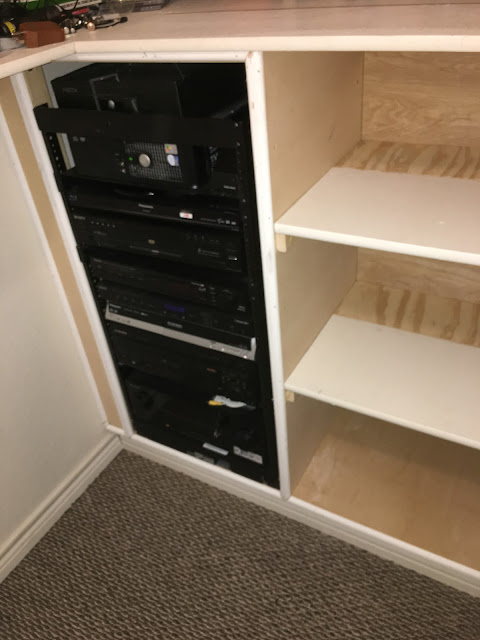
AV equipment rack.

Back a few posts I noted the laserdisc addition to the pile...

The house we moved into had a basic theater room, with everything wired into an equipment/storage room off the side at the back of the room.

I added a 24"deep shelf at the bottom of the existing shelves and widened the one above it to 24" deep., and just stacked stuff there, and on the other shelves.   It was a messy mess of wires, but it worked.   However to do anything required a lot of maneuvering.


(I didn't have a picture of the loaded shelf...consider yourself lucky)

I wanted something more useful, so did a bunch of research...and found out about equipment racks.

The one I settled on wasn't cheap, but made the most sense in my setup.


Yes the whole rack slides out...AND rotates!   In the above pictures you can see the frame I built to mount the thing on...it has to be sturdy enough to hold all the equipment without ripping loose.

This rack was a 19" one (standard 19" wide shelves)  like these...I ended up using one full depth shelf, the rest were these type shelves.


Here is the first filled rack...I have since rearranged it.


I continued to build out the rest of the enclosure...the idea was to make it look nice and be functional.  You can see were I widened the shelf just above the rack...I used on of the old shelves, and routed the back so it tucked in nicely with the bull nose shelf behind it.


Oh yea, the walls are scewed, like a trapezoid...so I had to square the center from the back wall, and gave the shelves a slight taper to they fit right in.


I reused a lot of material that came out of the original shelves, partially to be frugal, partially so the styling would match what was already there.


So in the above picture I used the original shelves, then added a piece of plywood to make them deep enough.  You can also see where now there is trim, and the gap at the left of the rack is filled.


Now backtracking a bit...I wanted the wiring to be somewhat orderly, out of the way, yet serviceable.   The rack takes care of most of that, but I knew there would be times I needed more access.   So, the shelves come out, the back panel comes out, and if necessary the right side of the equipment rack comes out.

So far I have already pulled the shelves and back panel to run some wire.

Now to the guts.


It is actually not bad for the first attempt...but all the cables were 6' to 12' long and so I had large coils...I am slowly removed all the long ones and puttin up ones that are just right.


Power is another issue, There were originally no plugs back there...so I wired into the one that I did have in the closet, and mounted two surge protectors back there...I don't have a power conditioner, but I do have a space to mount one.


You can see that the back of the rack has a stationary piece to tie all your cables into...then bind them together up high so they have somewhere to go when the rack is pushed back, signal wires are run on the opposite side of the rack.

And finally, the 'completed' working setup.


Tuesday, November 7, 2017

Outernet Dreamcatcher single board computer...with built in rtl-sdr

Like most people in this electronics hobby...I don't have near enough crap laying around.

So I read on the internets that Outernet was selling their SBC with built in RTL-SDR for $39...so of course I had to get one.


Specifically this board was set up to listen to L-band.

Outernet's goal is to provide free access to content from the web through geostationary and Low Earth Orbit satellites.

So it is a byproduct that this board can listen from 24Mhz to 1.5Ghz.

Let us begin...

For those of you (like me) used to Raspberry Pi images and support...well...


You can download a couple of different images but they are extremely bareboned...so expect to install a lot of packages to get things done.

Luckily, there are some basic instructional pages set up that can at least get you started.  And a lot of support on their forum.

However let me say that the hardware itself is much more capable than the pi, dual antennas, dual SD slots, 3 or so USB slots, and even a switch to power it on...in addition when you issue the shutdown command in linux it actually powers off...and there is a hardware button to power it on.

Let me warn you, that the board has no built in network or video.   So your admin will be remote.  The basic image lets you SSH in, but they only include a wifi USB dongle...so you need to supply a USB ethernet dongle to set up everything else (and so far I can't get the wifi dongle to work).

So my workflow was to first download the Armbian image.  (for the record, during my setups...I re-imaged this file about 5 times until I got it working the way I wanted)

Btw, unlike much hardware...the Dreamcatcher calls itself the Dreamcatcher on the network...so easy to find the IP address...I simply look at the router logs and make a permanent DHCP entry...what ever works best for you.


Next I did the usual updates, and installed tightvncserver.

Then I made tightvncserver boot with the device.

So now I had access to a GUI and SSH.

I have not yet made wifi work.  

BTW, there is no onboard wifi...however a wifi usb dongle was included.

Wifi was working as soon as I set it up...I just didn't realize I had to unplug the USB network card to use the wifi...unplugging the ethernet was not enough...or perhaps I am impatient...(it could go either way. )

For Wifi it is pretty simple.  The Armbian image comes with a program called nmtui

The usage is more simple than I realized...simply

sudo nmtui


You can do this in a Putty terminal, and you will still get a 'gui'.


I won't go into wifi setup...it is very intuitive through this GUI...  BTW the second screen is what you see when you select "Activate a connection"  If your network shows up on the list, then attempt to Activate it...if it doesn't, then use the "Edit a connection" and add one.


I tried a number of radio settings, but kept getting errors...however when I installed OpenWebRX, it worked perfectly and is a real nice remote rtl-sdr setup.  The Dreamcatcher is the server, and your other computer with web browser is the client.  However the remote client is not able to change frequencies...you can only do that in the config settings...so far...

Looks something like this...never mind the desk.


But with that limitation...it is terrific!

So, things to do...

I want to get APRS igate running...

I want to use YAAC...

I want to use a different radio program...


Friday, October 27, 2017

Raspberry Pi and touchscreens...Updated for latest Raspian (Stretch)


I have done a few other projects...that I might document in the future...

But this one seemed particular useful for me.

A very long time ago (mid 2000's) I bought a ~13" touchscreen panel with USB controller that I then stuffed into a Sharp display.   I fiddled around with making it some kind of keyboard/mouseless interface.   But at the time the winXP interface was flakey, and we were a long way from win10 tiles.

So I kind of parked it off to the side.

About 3 years ago we packed up and moved a few hours south...a year later I needed a VGA screen just to test some computer outputs...I looked for this monitor, but had no idea what box it ended up in or if I gave it to Goodwill.

When we moved, a lot of things were tucked away in the 1car garage shop...Two large boxes were stacked in the corner.  One was full of the wifes craft stuff...I assumed the bottom one was more of the same.

Nope.  The bottom one was full of pieces and parts, packed away on moving day 3 years ago.   On top was this touchscreen modified monitor.

I saw it and knew I wanted to mount a Raspberry Pi on the VESA mounts behind the monitor.   But the big question was would the Pi access the USB touchscreen.

I have a HDMI to VGA adapter that works perfectly so I hooked that up, and plugged the USB into the Pi, then fired it up.   The display still worked perfectly...and the touchscreen was read by the Pi...

(Note: read about the onscreen keyboard at the bottom of this post)

BUT...the calibration was way out to lunch and reversed.

A quick googling later and I found exactly what I needed, and my display interface (that shows up when you LSUSB) was even the same as the writeup.

This is the entire writeup.   But I only needed to do the following and now it is working perfectly!

------------------------------------------------------

The first test is if your touchpad reacts at all to your input...if it does (even if wrong) then skip to CALIBRATION section.

With later versions of Jessie, and the new Stretch, not all touchpad drivers (well at least the one I needed) are not installed.

So I had to do the following ,based on this forum entry

Install Evdev.

sudo apt-get install xserver-xorg-input-evdev

Then go to...

cd /usr/share/X11/xorg.conf.d

and list the files

ls

Mine looked like this...

10-quirks.conf     10-evdev.conf      40-libinput.conf     99-fbturbo.conf

The fix is to put the evdev.conf file after the libinput.conf file...the way to do that is...

sudo mv 10-evdev.conf 45-evdev.conf

then when you do an ls you get something like...

10-quirks.conf      40-libinput.conf   45-evdev.conf   99-fbturbo.conf

Finally reboot that, and the touchscreen should now be working...just out of calibration.

(In the calibration below one of the axis was reversed, when I did this on the Stretch install, they were not reversed)


---------------CALIBRATION-----------------------------

Calibration for the touchscreen(in Raspberry PI).
Note: The next steps are performed in the Raspberry PI's Debian Wheezy. This is a method for calibrating the touchscreen which will work just for Xserver and Xserver based applications.

Install xinput_calibrator.
Install some dependencies:

sudo apt-get install libx11-dev libxext-dev libxi-dev x11proto-input-dev

Download xinput_calibrator somewhere in the Raspberry PI's folder structure.

wget http://github.com/downloads/tias/xinput_calibrator/xinput_calibrator-0.7.5.tar.gz

Unpack it and then navigate to the unpacked folder and then install it using:

./configure
make
sudo make install

After this step you should run xinput_calibrator(from Xserver terminal console: first startx then open console and then run it).

xinput_calibrator

Follow the on screen instructions(touching some points on screen) and after calibration is complete you will receive a message like this:
Calibrating EVDEV driver for "eGalax Inc. USB TouchController" id=8
    current calibration values (from XInput): min_x=1938, max_x=114 and min_y=1745, max_y=341

Doing dynamic recalibration:
    Setting new calibration data: 121, 1917, 317, 1741


--> Making the calibration permanent <-- p="">  copy the snippet below into ...
<-- p="">
Section "InputClass"
    Identifier    "calibration"
    MatchProduct    "eGalax Inc. USB TouchController"
    Option    "Calibration"    "121 1917 317 1741"
    Option    "SwapAxes"    "1"    (only needed if the axis is incorrect...0 if correct)
EndSection


For Raspbian you have to create a file:

sudo nano /usr/share/X11/xorg.conf.d/01-input.conf

Add in this file the content above(starting with Section "InputClass" line) and then save it(ctrl+O).

Note:
Please make sure that you don't have sections like
MatchProduct    "eGalax Inc. USB TouchController"
in other files from /usr/share/X11/xorg.conf.d/ folder(highest number files are processed last, thanks to Jasmin).

Now touchscreen should be calibrated and after reboot it will keep the settings.
Once, I had to run xinput_calibration again in order to have the pointer to the desired points. You can update the numbers given by the xinput_calibration utility in the
usr/share/X11/xorg.conf.d/01-input.conf file in order to have the best calibration at boot.


------------------------------

Onscreen keyboard.

sudo apt-get install matchbox-keyboard

For some reason, sometimes the keyboard shows up in MENU > ACCESSORIES

This page describes how to display the icon using MENU > PREFERENCES. Main Menu Editor


In my case the Keyboard was already selected, I unselected it, re-selected it, and rebooted...then the icon showed up in the menu.

Friday, March 17, 2017

Communicating between multiple DVMegas or even OpenSpots on DMR without internet...revisited updated etc

 So the executive summary of this post is...

-SharkRF OpenSpots can communicate to HBlink (previous post)
-better install method for HBlink.


As far as the Openspot...the latest firmware (I have a v1.1 model) srf-osp-1.1-0101.bin improves the web interface and adds enough options to correctly link up to HBlink.
(I will admit, I only have one radio so right now I have not done a reception test...but the DVMega shows the traffic from the Openspot).

The Openspot manual shows how to do the settings...just point to the HBlink server, and use Homebrew/MMDVM Connector, and MMDVM Protocol.


The following is a cut and paste from a fellow ham, Mark who spent a lot of hours making a good repeatable installation process.  And in his setup, he runs HBlink on the same Pi that holds the DVMega...I am using a separate Pi.

-----------------------------------------------------------------------------------------------
This method does not require the loading of any specific versions of any of the components, which should allow it to continue to be usable in the future, even as the components are updated.

Note: I started with the latest 03/03/2017 raspbian release . . . even if you aren't currently using this release, the very first "sudo apt-get" step will actually update your RPi to the full equivalent of this release.

Note: if you have previously loaded other utilities (MMDVMHost, HBlink, or particularly ircddbgateway) on your RPi, you will need to edit any files in the /etc/apt/source.list.d/* folder (other than the standard raspi.list file . . . you can leave this one alone) & comment out any uncommented lines (e.g. particularly the references to nh6z.org, but also any others that may be present).  The uncommented lines in these files reference additional sources over & above those standard for raspbian & will very likely prevent you from successfully fully updating the raspbian OS on your RPi if they remain uncommented.

Here's the step-by-step that I followed to get HBlink installed & running:

sudo apt-get update && sudo apt-get dist-upgrade

cd /home/pi/Downloads

git clone http://github.com/n0mjs710/HBlink

git clone http://github.com/n0mjs710/dmr_utils

sudo apt-get install python-dev libffi-dev libssl-dev python-pyparsing python-appdirs

sudo pip install --upgrade pyOpenSSL pyparsing appdirs pyasn1 (that's digit one on the end of pyasn1)

sudo easy_install bitstring

sudo easy_install bitarray

sudo easy_install Twisted

sudo easy_install service_identity

cd dmr_utils

sudo python setup.py install

cd ../HBlink

cp hblink-SAMPLE.cfg hblink.cfg


(edit the hblink.cfg file for the following:)


under [MASTER-1]

change PASSPHRASE:
(to match brandmeister for convenience)

(passw0rd)

change PORT: (to match brandmeister for convenience)
(62031)


under [REPEATER-1]

change ENABLED: to False


Then, to run HBlink, you can use the same "startup script" + "autostart" method used for MMDVMHost.


Content of the /home/pi/.config/autostart/HBlink.desktop file is as follows:

[Desktop Entry]

Type=Application

Name=HBlink

Exec=lxterminal --geometry=120x32 -e "/home/pi/start_hblink"

StartupNotify=False

Content of the /home/pi/start_hblink script is as follows

(NOTE: in the command to kill HBlink, the character right after the "-9" & again at the very end of the command is a "back quote", which is typically somewhere to the left of the number "1" on most keyboards, whereas the character on either side of the "curly braces" after the "awk" command is a normal "single quote", usually located somewhere near the RETURN/ENTER key on most keyboards):


kill -9 `ps -ef | grep -v grep | grep "hblink.py" | awk '{print $2}'`

clear

echo -n "sleeping 10 seconds before (re)starting HBlink."

sleep 1

echo "."

sleep 1

echo "."

sleep 1

echo "."

sleep 1

echo "."

sleep 1

echo "."

sleep 1

echo "."

sleep 1

echo "."

sleep 1

echo "."

sleep 1

echo "."

sleep 1

echo "."

clear

cd /home/pi/Downloads/HBlink ; python hblink.py


In English, the command line to kill HBlink says to do the following (in this order):
1) [ps -ef] = get a list of all tasks that are running

2) [ps -ef | grep -v grep] = take the results from #1 & ignore any task that has the word "grep" in it

3) [ps -ef | grep -v grep | grep "hblink.py"] = take the results from #2 & filter it down to only those tasks that contain the text "hblink.py"

4) [ps -ef | grep -v grep | grep "hblink.py" | awk '{print $2}'] = take the results from #3 & print out the task ID number which is in the second field (where fields are considered to be separated by a "space" character by default)

5) kill -9 `ps -ef | grep -v grep | grep "hblink.py" | awk '{print $2}'` = execute the whole command string in #4, take the results from #4 (which is a task ID) & hard kill that particular task ID, no matter what

(If like Mark, you run HBlink on the same Pi that has the DVMega mounted then...)

When running MMDVMHost & HBlink on the same RPi, you must configure MMDVM.ini as follows:

[DMR Network]
Address=127.0.0.1

(Normally that points toward the remote brandmeister or whatever server)

I tried using the RPi hostname in this setting, but in that case, MMDVMHost does not fully complete the registration process with HBlink

Feel free to use this info however you see fit !!  -Mark


Tuesday, January 17, 2017

Communicating between two DVMEGAs without access to the internet

So previously I installed the DVMEGA hardware onto a Raspberry Pi, and installed an image running MMDVMHost which makes the DVMEGA-Pi into a digital radio hotspot...specifically in my case a DMR hotspot.

It is very handy in my application...that is my house is apparently a faraday cage and no radio signals shall pass.

But what if you are out in the field with no access to the internet (no Brandmeister) and too far remote to reach a repeater...how can you use your DMR capabilities?

I dug through the internets for a while until I stumbled over some open source software developed apparently to run full size repeaters.

HBlink   https://github.com/n0mjs710/HBlink

So here is the scenario.  You have your mesh network setup, but the internet is not connected to your MESH.   You have two or more DVMEGAs deployed at different locations...and obviously you have DMR radios at those locations.  With an additional Raspberry Pi running the HBlink software somewhere on the MESH, and the DVMEGAs pointed toward it, now your DMR radios are doing their DMR thing within your MESH network.  (or another way of looking at it is a private DMR network)

This will be a quick walkthough of the software install and config...pretty straight forward, and I am not a Pi genius.

I started with the latest Raspbian Jessie with Pixel.  https://www.raspberrypi.org/downloads/raspbian/

For my purposes I used raspi-config to enable SSH and VNC...

Once all the reboots are done and software updated...

--:   sudo apt-get update

and install the python-dev tools for our Jessie version of Raspbian.   If you don't do this step the rest of the installs will not work.

--:  sudo apt-get install -t jessie python-dev

Then I opened the Pi's browser and downloaded the following software. (in all cases I downloaded the zip or tar.bz2 or tar.gz file)

Bitstring 3.1.5
https://pypi.python.org/pypi/bitstring

Bitarray 0.8.1
https://pypi.python.org/pypi/bitarray/0.8.1

Twisted 16.3.0  (download the Source)
https://pypi.python.org/pypi/Twisted/16.3.0

service_identity 16.0.0  (download the Source)
https://pypi.python.org/pypi/service_identity

DMR_utils
https://github.com/n0mjs710/dmr_utils

HBlink
https://github.com/n0mjs710/HBlink


Then using the File Manager in Raspbian I went to the downloads folder, right clicked on each file individually and selected "Extract Here"

I did the following steps within the terminal window.  These were all python scripts, and all installed the same way.

--:  cd Downloads

We will start with service_identity.


--:  cd service_identity-16.0.0
--:  sudo python setup.py install

after it finishes downloading and installing

--: cd ..

and so on and so forth through the rest of the downloads

--:  cd bitarray-0.8.1
--:  sudo python setup.py install
--: cd ..

--:  cd bitstring-3.1.5
--:  sudo python setup.py install
--: cd ..

--:  cd Twisted-16.3.0
--:  sudo python setup.py install
--: cd ..

--:  cd dmr_utils-master
--:  sudo python setup.py install
--: cd ..

--:  cd HBlink-master
--:  sudo python setup.py install

now stay in the HBlink-master directory...we need to edit the hblink.cfg file...there is none, but there is a sample to be edited.

--:  nano hblink-SAMPLE.cfg

scroll down until you see [MASTER-1] ...make it look like this.

[MASTER-1]
MODE: MASTER
ENABLED: True
REPEAT: True
EXPORT_AMBE: False
IP:                                                             (I left this blank...seems to still work)
PORT: 54000
PASSPHRASE:                               (I use the same one I used for brandmeister...)


I also scrolled down to [REPEATER-1] and set ENABLED: False

now within nano save the file, but change the name to hblink.cfg

(for nano editing, the CTRL key and whatever option you want...so to save = CTRL-o   ; to quit = CTRL-x)

We are done installing and configuring.

To run, simply type (we are still in the HBlink-master directory)

--:  python hblink.py

You will see some messages like

-DEBUG - Logging system started.
-INFO - HBlink - SYSTEM STARTING...
-DEBUG - (MASTER-1) Master maintenance loop started
-DEBUG - MASTER instance created

if you see anything other than that especially with words like FAIL or ERROR...you probably have a problem...google is your friend.

After those start up messages you will simply see the 'DEBUG Master maintenance loop started'  message every few seconds...

Now on your DVMEGA, edit the MMDVM.ini file to have the DVMEGA use the HBlink machine as the server.

[DMR Network]
Enable=1
Address=xxx.xx.xx.xx        (your HBlink machine IP address goes here)
Port=54000                          (the HBlink port#...)
# Local=3350
Password=s3cr37w0rd      (make this password match the one you put in HBlink)
RSSI=0
Slot1=1
Slot2=1
Debug=1

At this point start up MMDVMHost  (personally I just reboot the DVMEGA pi)

If you are watching the HBlink screen you will see the following message when the DVMEGA logs into it.

-INFO (MASTER-1) Repeater Logging in with Radio ID: xxxxx,
-INFO (MASTER-1) Sent Challenge Response to (your DMR ID) for login:
-INFO (MASTER-1) Client (your DMR ID) has completed the login exchange successfully
-INFO (MASTER-1) Client (your callsign and DMR ID) has sent repeater configuration

now when you kerchunk your DMR radio to the DVMEGA you will get the following message on HBlink

-DEBUG (MASTER-1) Received and answered RPTPING from client (your callsign and DMR ID)

after some inactivity you will get

-INFO (MASTER-1) Client (your callsign and DMR ID) has timed out


that RPTPING is all you need to see to know it is working...of course the DVMEGA machine should successfully login to the DMR server also.


Now from this point all you have to do is point the DVMEGAs to the HBlink server and it is all up and running.   I successfully tested this using two DVMEGAs set 5Mhz apart in freq, connected through different nodes of the MESH, the server and the DVMEGAs were on different nodes.