Wednesday, February 6, 2019

Small Oscilloscope kit review


I somehow hadn't heard about this kit until recently...I saw one on a video about the same time a friend showed up with one.  I got this one off Amazon (I am not a shill...so I didn't post a link to a particular one...but this is the title description)

JYE DSO 138 DIY KIT (13801K)


I also got a plastic box for it...funny that Amazon does not recommend this box, and doesn't say it will fit...but yes it will fit.  (I don't know if other brands will work...I have this one)

 Diymore DSO138 2.4" TFT Digital Oscilloscope Acrylic Case DIY Kit (Acrylic Shell DIY Kit))

 The Oscilloscope kit (and apparently there are many knock offs...based on this I think I have a knockoff unfortunately) was straight forward thru hole soldering...there are some pre-populated SMD items, the board is large enough that it is not difficult placing and soldering the components.

It only took a couple of hours or so to solder together, the instructions are good, the components are not well labeled to match the instructions, but it is fairly easy to decipher what goes where (specifically the different capacitor values if you are not familiar with the coding system they use)

I would recommend that you first separate all the components and group them based on item number (R1, R2, C1,C2, etc)   I have a small magnetic mat, with a pre-marked grid, that I just numbered 1-10 and dropped the correct components in...again to make ID easier...I kept them in groups...because there may be one of a particular value but 5 of another...so between label deciphering, and deductive reasoning I could ensure I put the right thing in the thing.

There is a step prior to final assembly to test that you haven't screwed it all up.  Assuming nothing is wrong, you do final assembly and power it on.

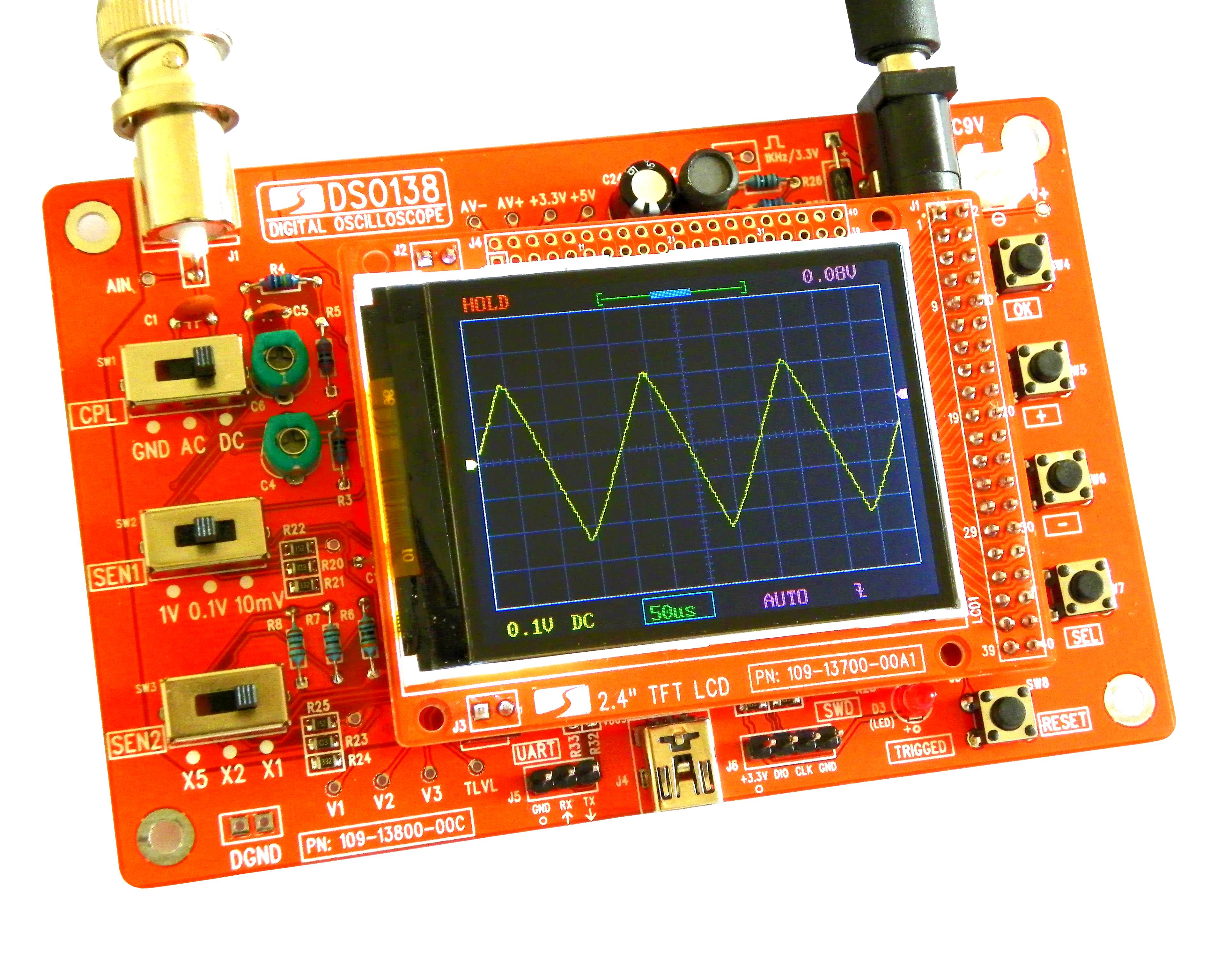
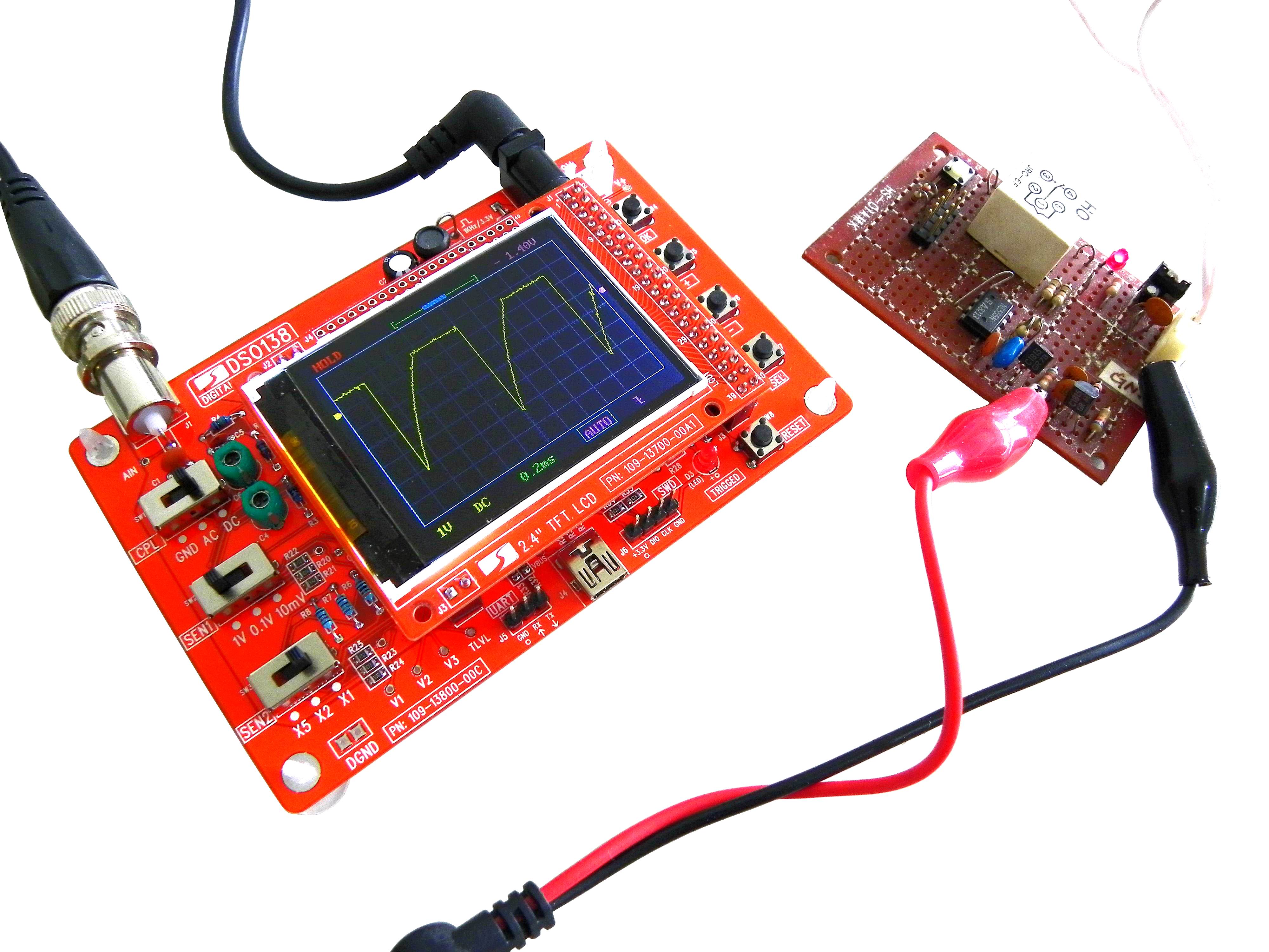
I was very surprised at how well it worked.  I have a regular O-scope, so I know what it should look like, do, and how it should operated.   It works just like a mini scope, many bells and whistles I didn't expect to get...

Selectable GND-AC-DC coupling,
1v .1v .01V  grid
X5 X2 X1 expansion

..and a clunky button menu system for timing values etc.

I can't say I would recommend this for real precision work, but if you want a simple O-scope...this works just fine...If you need a pocket (large pocket) sized portable O-scope for quick signal checking, then for the money you can't go wrong with this one.

Tuesday, February 5, 2019

Gizmo Arpeggiator etc

I recently aquired a Yamaha DX7 that needed a tiny bit of maint to bring back to working order...It cost me $1 to fix.   I got really lucky with a really nice keyboard. (the backup battery powers all the ROMS...you can replace it with a holder and coin cell battery)

So I am fiddling around with voices (or patches or specifically Sysex files).   But I am not getting enough...

Randomly I see a YouTube video about Arpeggiators...and specifically DX7 Arpeggiators.

BTW, I am not a pro musician, and I do not understand the math behind this...

So I start searching for an Arpeggiator.  I stumble upon a device that tickles my hardware hacker cockles... Gizmo.

"Gizmo is the codename for an open source MIDI utility device which targets the Arduino Uno or Mega."

Gizmo was done (as far as I can tell) as a music theory thesis.   The documentation is the thesis, so it is a bit hard to wade through...but it is all there.

It is an Arduino, with some code and a MIDI hat on top.   The code utilizes the MIDI hat switches and rheostats to control the software.


The code seems correct..but it is very challenging to wade through, so I am only going to demo the Arpeggiator function.

(I am using a Mega and the MIDI hat)

The short version is the software utilizes the midi functions of the keyboard to manipulate other keys...giving a more complex sound than would normally be generated.

So in my case (DX7), the MIDI-OUT from the keyboard goes into the MIDI-IN on the MIDI shield, and likewise the MIDI-OUT from the shield, goes to the MIDI-IN of the keyboard. (it seems to be a Yamaha thing...my MIDI USB card is wired up the same way.)

I followed the instructions...but I kept having a compiling error...I fought it for days, then realized that I had two temp files that were fouling up the process.

(wire.cpp and wire.h)

Specifically, the instructions to run the code require two edits to standard  wires files.   My solution was to search for those two files on my computer and delete the ones that weren't  the primary files.  (It will make sense when you follow the instructions).

Anyway, this is the demo...not sure why the video was suddenly so dark...but at least the audio was ok...you will notice first I do the audio without the Arpeggiator running, then with it running.


LED Panel display 16x32 for $14.

Update at end:


I recommend you follow on YouTube bigclivedotcom in particular a few weeks ago he showed this video...

The summary is,  a toy 'handbag' that has a standard (75 hub) 16x32 LED panel, that you can get on ebay for about $14.

Bigclivedotcom does the teardown etc...

I will fast forward to application.


Because it is a standard 75hub display, you can use Adafruit's data to install and use.  Here is the software code for Pi.

I am using a Raspberry Pi with the RGB Matrix HAT to drive the display.  For cables I searched for 75hub cables and found these at Amazon.   These LED boards have 4pin power plugs, so eventually I found a bag of these.  And these panels only had one connector...so I needed to solder some on to daisy chain the data lines.  I got these from Digi-Key.

Note the high tech blue painters tape...this is just to support it while I test it, the Pi and LED driver board are under the bluetape.


The first panel worked so well...I bought 3 more...and because these displays are designed to be daisy chained...

Some examples of the code and output.  located in this directory.

cd rpi-rgb-led-matrix/examples-api-use/


sudo ./demo -D 0 --led-rows=16 -b50 --led-chain=1 --led-pixel-mapper="U-mapper"


sudo ./demo -D 0 --led-rows=16 -b50 --led-chain=2 --led-pixel-mapper="U-mapper"


sudo ./demo -D 0 --led-rows=16 -b50 --led-chain=4 --led-pixel-mapper="U-mapper"


For the next two you need to specify a font...and specifically a .bdf font...luckily they are included.


 sudo ./scrolling-text-example -f ../fonts/helvR12.bdf -b 75 -s 3 --led-rows=16 --led-chain=2 There is another...


sudo ./scrolling-text-example -f ../fonts/helvR12.bdf -b 75 -s 3 --led-rows=16 --led-chain=4 There is another...


I am just figuring out the software, and I want to make a mount so that I can swivel the two upper panels to be in a row with the lower ones for some applications.


After playing with this, I found this write up.  So that is what is on my sign now.  Here is the Github.

BTW I changed the time display in this rgb-32x64.py code from the writeup.

around line 439

original code was [  text = datetime.datetime.now().strftime("%H:%M"]

now it is [  text = datetime.datetime.now().strftime("%H:%M Local") + '  ' + datetetime.utcnow().strftime("  %H%M UTC  ") ]

That displays the time as   9:45 Local    1545 UTC   (depending on your time zone obviously)

You could probably add more time zones, but that adds a level of difficulty.


Premier Pro CC jog/shuttle dial

I (for fun not profit) do video editing on Adobe Premier Pro.   It is a very powerful program...and I am terrible at keyboard shortcuts, so I mouse everything.

One important part of editing video is finding where you want to start and end a clip, then copy/cut and paste it somewhere.

The cut and paste of PP is pretty straight forward, a chop then drag and drop.

The finding the start/end is the hard part.  And it is a pain with the mouse.   I had a Griffin Powermate Jog shuttle dial that plugs in to USB and you can program it to simulate key presses.

Unfortunately they softare stopped being supported with WinXP, I could run it in Win7 but it would occasionally cause the computer to crash, and completely died by the time Win10 came out...so it was a USB powered paperweight.

BTW it was not recognized natively by any version of windows, it REQUIRED it's software to be running.

So for the last few years I have done without a jog shuttle dial, and continuously scoured the internets for a solution, there are a couple of $1000 solutions...and a $99 one, but the $99 dollar one does not have the ergonomics I wanted...it was too big...about 3 times the size of my Powermate.

Just a couple of weeks ago I was again looking for the J/S and found this article...I was sold, I order parts and soldered them up...then I realized that the parts looked like they might just fit inside my old unused dead Powermate.

So I undid my soldering and got to fitting.


The rotary encoder was a loose fit at the top, but that was fixed with a rubber o-ring.   It  was also a bit long to be centered, but I was able to trim off some of the rotary encoder board so it would fit.

The Arduino Leonardo board was just slightly to big for the spot I put it, however I was able to use a Dremel to cut a bit off the metal Powermate and it tucked right in.


 I also needed to remove the micro USB port, and I direct soldered the original PM USB cord.


In fact the install looks almost identical to the original PC board that was in it.

So with hardware done, I did the normal Arduino stuff to load the authors code into the Arduino, fired up PP and the new J/S worked right away.  

The Arduino program simulates keypresses, so you have to choose which code to install.  

I used the "PremierProDialDIY_LEFT_RIGHT_SPACE.ino" file...the space button in PP is the playback start stop...push down on the rotary encoder to activate that.

Another choice is "...LEFT_RIGHT_CTR_k..." in that case CTR_k is the hotkey to cut...I am afraid I would make accidental cuts.

The author has a new software that cycles between the Lightroom setup and the PP setup, software for the Sony Vegas hotkey...I am only using it with PP.

BTW after looking at the original Powermate pictures...I realize I removed the bottom at some point to try and fix it...I now need to find that piece...

I have 3 or 4 projects to document

I have 3 or 4 projects that I have had completed for a while, but hasn't yet documented.

So I need to get on that...it is easier to do than document...