Wednesday, December 9, 2020

Link SIP phone throuhgh PBX to Allstar Node.

 I honestly have no idea why someone would want to do this...but I done it anyway... making a PBX so I could  do all the things made some sense...linking the PBX (asterisk) to the Allstar node (asterisk) seems ridiculous.


So here is how to do it.  (this is more of a quick and dirty reference rather than a walk through explaining everything)


Background...in 2018 I built an Allstar Node using a cheap radio and a Raspberry Pi.  My access to control it was either DTMF on the radio, or logging in using the built in web page.


Also a couple of years ago I got a Hamshack Hotline number and had that on my SIP phone.


(some other things were done...time passed) 


And just now I built a PBX using Incredible PBX on a Raspberry Pi.


So obviously I would link the Allstar node to the PBX.   Trust me, there are much more advanced set ups that folks have done with Asterisk and radios...Such as K8JTK's multimode hub.


Anywho it took a day of pain and watching error screens before I got the solution...and the first verified solution did not work at all...maybe I typo'd something, but it was wrong.


This won't be full of info, because it is pretty simple...it is just the terminology that is difficult.


If  you built a PBX then you know some of these terms already.


Big picture is Allstar uses Asterisk to do all the heavy work, the DTMF controls the hub linking etc.

Incredible PBX (FreePBX) ALSO uses Allstar for all the heavy lifting...it just has a pretty GUI to make admin easier.


What we will do is connect two peer Asterisk servers.   Allstar <-> Incredible PBX


To do that we will Trunk them together using the IAX protocols.

That means, on Incredible PBX we will ADD a IAX Trunk.


If you already have the Allstar node, then you are already used to editing the various .conf files.


We will edit two of them.  iax.conf and extensions.conf     (if you were to connect a SIP phone to the Allstar node directly you would edit sip.conf and externsions.conf. SIP for phone, IAX for server)


IAX.conf is basically the 'add IAX Trunk' for the folks that like using the linux terminal.

[pbx2_to_pbx1}
host=(IP address of PBX2 goes here)
username=pbx1_to_pbx2
secret=UseALongPasswordNumbersLike1234AreOk
type=friend
disallow=all
allow=ulaw

[pbx1_to_pbx2]
host=  (IP address of PBX1 goes here)
username=pbx2_to_pbx1
secret=UseALongPasswordNumbersLike1234AreOk
type=friend
context=radio-control
disallow=all
allow=ulaw

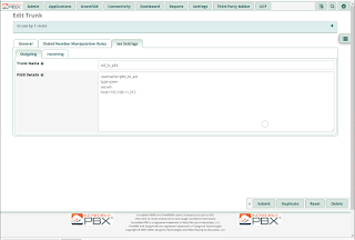
So those two matching entries are the Trunk entries or IAX.conf entries, depending on which device you are working on.   The HUGE hint is to look at the name in [brackets] that is the TRUNK name.   Note also that the OPPOSITE machine uses that TRUNK name as USERNAME and vice versa.   That lets the two Trunks to talk to each other.

Not understanding that, and following the wrong instructions took a day to figure out.


You will note in my screenshots that I didn't put all that stuff in it...but the important takeaway is the relation of the "Trunk Name" in the OUTGOING section of the Trunk entry to the username of the Trunk in the machine you want to link to.


The other edit required is in the  extensions.conf   again note the name in [brackets] it has to match the "context=" value in the Allstar node IAX.conf.


So how does it work?  I select the same extension I am using for GV,  punch in my Allstar node number, the PBX connects my phone to the Allstar node.  From there I punch in the codes to connect to outside nodes...or just listen to what is coming over my node.   I haven't done any speed dials etc yet...


Some links.

I used this to make the extensions.conf

Here is where I learned the correct format for the iax.conf/Trunk entries

Some screenshots.


Monday, December 7, 2020

GoogleVoice through Obi200 to IncrediblePBX (FreePBX) on a Pi4 (part3)

Parts one and two had to do with setting up the Obi and Phones.

It doesn't matter in what order, I think it makes  more sense to me in this order.


The PORTS used depend on what SP you use etc...the screen shots are of mine...if you use a different config, then doublecheck the ports...mine are consistent, so you can start with your Obi and convert from mine to yours.

Also btw...I removed my GV number from the caller ID spots in the pictures...but it was only in a few places that I should have mentioned...if I didn't mention caller ID, then you probably don't need to put the GV number in...in other words there are blank caller ID spots and filled caller ID spots...I think CID is only need in two spots.

I will not get into installing Incredible PBX.  BTW, if you are googling for help you can use FreePBX also in your search...the menus are the same.


This last part is the settings I used to get the PBX to talk to the Obi,  For the Phones to talk to the PBX, and for the phones to make calls and ring, and even intercom.


First...PBX talks to Obi.

Log into your Incredible PBX as Admin  (when you installed you should have created a new password?)

We are starting from zero...nothing other than default entries on the PBX.

After each step, hit submit...when done with a section click the Red button in the upper right that says Apply Config

 ---------------------------------

You need a Trunk.


Click on Connectivity > Trunks


There are a ton of Trunks there for using all sorts of VOIP phone services...I am not using those, so I deleted all the trunks.


+Add Trunk > +Add SIP (chan_sip) Trunk     (I could not get anything to work using the pjsip anywhere                                                                             in my install...just plane old legacy SIP)

General Tab

Trunk Name = {something useful to you  - I used obi200 to match the Obi settings}

Outbound CallerID = {your Google Voice number}

sip Settings Tab

 type=friend
defaultuser=obi200
secret={password you put into the obi}
qualify=yes
port=5062
nat=yes
host=dynamic
dtmfmode=rfc2833
disallow=all
context=from-trunk
canreinvite=no
allow=ulaw
insecure=port,invite

 Thats it for Trunks.

 ---------------------

 You now need an Outbound Route


Delete any existing Outbound Routes, or you will have a bad time.


Route Settings Tab

Route Name = {something useful to you - I chose OBiOut}

Route CID =  {same Google Voice phone number}

Trunk Sequence for Matched Routes = {you just built it... obi200 for me}

Dial Patterns Tab

You can try to learn them...or just click the 'Dial patterns wizards' and select all the appropriate ones


Thats it for Outbound Route

 -------------------------------

We will have to do the Extensions before we do anything else...these are the different physical phones (in my case) you want to access the PBX.


Applications > Extensions

There will already be a bunch there and you can use them...or roll your own...I rolled my own and did some experiments, so there are some extras there...don't worry about them.

They are pretty simple.

+Add Extension > +Add New SIP (Legacy)[chan_sip] Extension


again, I could not make the pjsip extensions work...my phone wouldn't log in, and it wasn't worth it to fight it.

If you edited your phones and gave them numbers like 201, 202 whatever. you make an Extension for each one.

In my case I have two, 200 and 201.  (ignore the others in the pictures)

So 

General Tab

Extension = 200 {whatever you put in that particular phone}

Display name = 200 {or whatever you want}

Secret = {same password as you put in your phone}

That is all you NEED to do...you can add voicemail etc...that is beyond the scope of this article.


Once you have made an Extension for each phone...you are done.  (BTW the user manager settings are to allow logging into a user dashboard)

Now I have two Extensions...and probably my phones are showing online...but we aren't done yet.

------------------

We want to be able to answer the phone.   If you wanted only one phone to ring you would set it up a bit differently from here...


...but I want all phones to ring, so I can pick up whatever extension I am near.


So I need a Ring Group


Applications > Ring Groups

+ Add Ring Group

 Name= {some number, this is considered an extension, I made it 222}

Group Description = {anything you want, sales, admin, or in my case bothphones}

Extension List = {all the extensions that are in this particular ring group...in my case both phones, yo

u                                 can use the User Quick Select. In my case 200 and 201}

Ring Strategy = {this is awesome...so many choices...but I simply want all the phones to ring                                            simultaneously so... ringall}

Destination if no answer = {for now I have an extension chosen...but voicemail is probably a good choice...outside the scope of this discussion}

You are done with ring groups...

-----------------------------

NOW time to do the Inbound Routes


Connectivity > Inbound Routes

(there should not be any old routes here...if there are, delete them)

+Add Inbound Route

Set Destination = Ring Groups   {and select the Ring Group extension you created - in my case 222}


That is it for Inbound Routes.

--------------------------------

Bonus section


Put all the phones on intercom...

Applications > Paging and Intercom

+Add Page Group

Paging Extension = {this is the phone dialpad sequence you type to start the intercom -  in my case 22}

Group Description = {whatever you want}

Device list = {pulldown - which extensions do you want involved in the paging - for me all of them}


Done with paging.   When I select the PBX line (EXT3 on my SPA504) and type 22 on the dialpad, all the phones (both) go on speakerphone and connect to each other.

----------------------------

That is everything I modified...and attached are my screen shots in case something doesn't make sense.   If it doesn't work, break down WHICH part doesn't work.


Some examples...I could phone in and one phone would ring, but I couldn't call out.  I had to delete the default (extra) outbound route to get the phone to dial out.

Only one phone rang during ringall...because one of my phones was not set up to Register on the PBX.

lines wouldn't connect to the pbx at all...because phones wouldn't use pjsip extensions

Latest example...one phone could dial voicemail and the other couldn't...the one that couldn't had just XX in the dial plan...it needed to be (*xx|[3469]11|0|00|[2-9]xxxxxx|1xxx[2-9]xxxxxxS0|xxxxxxxxxxxx.)


Pics...lots... hope it helps someone ... Of course there is much more to set up...but this gets your phones working.


GoogleVoice through Obi200 to IncrediblePBX (FreePBX) on a Pi4 (part2)

 Part one had the settings to edit on the Obi200.


This part will cover two Cisco Phones a SPA504G and a SPA525G  these are SIP phones, and the ones I have are unlocked (not associated with any carrier).

These settings will allow the phones to be able to access the PBX for calling etc.

I will have to assume you know the basics of how to get to the admin page of your phone and how to enable lines etc.

Again, my PBX is at 192.168.11.45

For my setup...I put the PBX Google Voice line on Ext3 on the SPA504, and Ext4 on the SPA525, it doesn't really matter...just make sure you enable those Extensions and put them on Line buttons.

Everything I don't list is default from factory refresh.

EXT3

SIP Settings

SIP Port: 5062

EXT SIP Port: 5060

Proxy: 192.168.11.45

Outbound Proxy: 192.168.11.45

Alternate Proxy: 192.168.11.45  (I don't know if I had to fill them all in...but I did anyway)

Register: YES

Subscriber Information

Display Name: {whatever you want}

User ID: {an extension on your PBX I went with the 200s so this one is 201}

Password : {enter the same one on the PBX extension area for this extension}

Auth ID:  {same as User ID - again I used 201 here}

Dial Plan: (*xx|[3469]11|0|00|[2-9]xxxxxx|1xxx[2-9]xxxxxxS0|xxxxxxxxxxxx.)

Every other phone will have a different extension.


GoogleVoice through Obi200 to IncrediblePBX (FreePBX) on a Pi4 (part1)

 Long time no post.   Been doing stuff...but nothing completed, or worth documenting.


However this battle took days and the docs and instructions I found assumed you knew something.  (they were wrong).

BTW...some good links...

Documentation on all the settings for FreePBX (Incredible PBX)

Obihai support page

Obihai support video on how to set up Google Voice on Obi200

Nerdvittles article on setting up Incredible PBX on your Pi

How to set up your system so email works 


In summary, I installed the Incredible PBX (using an image) to the Pi4.   (I won't get into what a PBX or Asterisk or anything else is...this is simply my settings.)


Right now the only way to use a GoogleVoice phone number is through an Obi device (Polycon?)

I have an Obi200 that gives me a regular POTS phone line to plug into, but used a VOIP service on the other end...for example Google Voice.


I recently learned how to make an entry to the Obi that would allow a SIP phone (like a Cisco SPA504g) to call and answer on that Google Voice number.  (this won't explain that...I will link it)


A few months later I learned that I could take a PBX software, and have it call and answer through the Obi to Google Voice...AND then can have any number of SIP phones attached to it.  So instead of one SIP phone...a whole house full of them (if I so desire).  


Why would I care? I am already using a SIP phone for things other than my Obi telephone service.


So this string of posts will only involve taking your existing GoogleVoice setup on your Obi200 and pushing it out to IncrediblePBX and from there to SIP phones.


Part 1: I will start with the OBI settings in this post .   I don't know exactly why these are the settings...it just works (and some are different than all the tutorials I found) 

Part 2 will cover the phones and part 3 the Incredible PBX settings.

--------------------------------Danger Ahead-----------------------------


If you mess up your existing working Obi...not my fault...but I recommend that before you do this, you make a backup (or like I did, actually take screenshots) so you can put it back.

Good news is this does not involve editing the Service Provider settings of your existing GoogleVoice install...it does add one thing to the SP service associated with your GoogleVoice install.

To start, you have to enter the Obi Expert Configuration Menu on the Obi Dashboard (not your local device dashboard)

We will be working with the following that show on the left menu after you enter expert mode on the Obi

Service Providers: listed as A-D

Voice Services: listed as SP1-SP4 and some other stuff

I will try to list my setup, so you can modify to fit your setup.

 Service Providers:

ITSP Profile B is my Google Voice  main inbound service - we will not edit this.

ITSP Profile C is unused, I will connect my PBX to this profile

Voice Services:

SP2 Service is for Google Voice main inbound service - tiny edit here

SP3 Service is unused, I will my PBX will use this service


Obi is at 192.168.11.32

PBX is at 192.168.11.45

One cisco phone is at .33 and one is at .35 


To edit the Obi Expert Menu, you have to uncheck OBiTALK Settings, and then uncheck Device Default...sometimes you have to 'submit' there to go further...IDK.

Edits---

Service Providers > 

ITSP Profile C General

-General

Name = {whatever you want}

-Service Provider Info

Name ={same as above}

URL = {PBX ip address}


ITSP Profile C SIP

ProxyServer = {PBX ip address}

RegistrarServer = {PBX ip address}

OutboundProxy = {PBX ip address}

 ...

X_SpoofCallerID {uncheck Obitalk settings and Device default, check Value)

X_DiscoverPublicAddress {uncheck all}


Voice Services > 

SP2 Service

-Enable

X_InboundCallRoute = ph,SP3           (in my setup, the POTS phone is still connected and still rings)

                                                               (SP3 is for the PBX)

SP3 Service

-Enable

X_ServProvProfile = C    (because I created ITSP Profile C they go together)

X_InboundCallRoute = >(MSP2):SP2    (don't ask me what this does...but SP2 is where GV is)

X_AcceptSIPFromRegistrarOnly {check Value, uncheck the others}

X_KeepAliveEnable = {check Value, uncheck the others}

-SIP Credentials

 AuthUserName = {pick something, but you will use it on your PBX, I used obi200}

AuthPassword = {I put one in, but the check mark keeps going to Device Default...yet it works...}

                             (you will use the password on your PBX)

-Calling Features

MaxSessions = {something larger than 1...I used 6}


Some of those settings might be wrong, there may be better ways...but it works.  At the end I will attach the screen shots so you can compare notes.


On to Part 2 the phones.


Monday, April 27, 2020

Supplemental files... DG-10 to DG-20 MIDI conversion

Ok...this is simply going to be all the files...I will try to organize them by section...starting out with the MIDI conversion.

This is what I used to do my mod.

First it is very handy downloading the DG-10/20  Service Manual available many places... 

On all the documents I annotated the original wiring in red (so I could follow the circuit) and my changes in pink (basically as an assembly manual).

The most time consuming part was the re-engineering...but soon I realized that the schematics almost exactly matched the circuit board...so you could almost lay the schematics over the board to identify parts.

In my reverse engineering I reversed the pictures of the bottom of the circuit board so it would directly match the top of the board...and the schematic...it makes sense once you try it.  As a result some of my notes are in backward writing, but it is easy enough to figure out.

Lets start with the schematic.  

First starting with the MIDI port on the DG-20.  There is a switch to either have 6 channels out...or just all 6 strings to one channel.   Second is the port itself.   Note the identifiers JG-1 through JG-6  This is on a daughter board at the IO jacks...I had to just wire it up direct.  (BTW the item marked FB...those are ferrite beads) (I used DigiKey part number 240-2513-1-ND Ferrite Bead 86 Ohm Axial)  Also on the circuit below, there are two things that look like black circles spit in half...they probably match something on the circuit board that would have been mounted on the DG-20...I couldn't even see a photo of that board...the fully split in half one means not connected...the one with a small line in the middle is connected...


 Now on this schematic on the upper left side you again see JG-1 through JG-6 , these are the drilled holes in the DG-10  circuit board...they aren't marked...and I did have to modify them a bit...but it is almost 100% there.  So I ran wire from those drilled holes to my MIDI connector and switch.


Now you will note on the DG-10 schematic the obvious missing JG connection.  You can see in pink the required mods...one specific one tells the CPU that it is a DG-20 not DG-10


So here is what it looks like on the DG-10 circuit board.


 Inverted backside with mods  You will note I marked the connection 1-6 on the upper right side.

BTW all the jumpers and components go on the top...but it was easier to follow the circuit by drawing it out on the bottom of the board.


Actual view backside with mods, again red is existing wiring, pink is my mods.


These photos have ALL the mods in view, not just the MIDI...so just using the schematic, knowing where i marked pin 1 and 6, just follow the lines... There is one wire to remove, a resistor to add, a diode to add. and a handful of jumper wires to install...almost everything goes into existing drilled but not marked holes.  Now for the pic below, note the wires at the lower left of the above pic.


 Here is the only circuit trace you have to cut...right there in the center of the pic above next to "JD" you see I have a pink line and 3 white lines...that area is one big circuit trace, so I had to cut it where those lines are to separate the area into separate traces...the white is where I dug through the copper trace to bare circuit board below.


Finally I needed to know what pin is what for the MIDI connector.

Going slow and using a voltmeter in 'resistance...beep' mode I went through it line by line, making sure I had a match from the schematic to my DG-10 wiring.


Friday, January 10, 2020

Casio DG-10 modified into a DG-20


So if you were a rich kid in the 80's you might have had a DG-10 or DG-20 a digital guitar made by Casio.  ($350 for the DG-10...I am guessing the DG-20 was $50 to $100 more)


I was not a rich kid in the 80's and I hadn't even heard of this until I saw one on the remake of the Take On Me video by Weezer.


So I did so looking around, figured out what the device was, then tried to by one.


I lucked out and picked up a DG-10 (like in the video)  that needed a bit of work but operated just fine...for dirt cheap...

So I got it running and played with it a bit, as I dug through the documents available I learned that I had the stripped down version, but there was also a DG-20 that had line out and MIDI out. (as well as some other sound and manual percussion switches).

Well I was jealous of the MIDI output...so I popped mine open to see how hard it would be to modify mine to add MIDI support.

I noticed that in the Service manual that the main parts seemed to be identical and even the circuits were almost identical except for some minor differences and some passive components.

I took pictures of the circuit boards top and bottom and happened to find a few pictures of a DG-20's guts.

I realized that those geniuses at Casio had built both keyboards with the same chips and almost identical circuit boards except for about 3 modified traces...depending on which version you got, some traces were whole and some were cut.

The circuit boards even had the drill holes...the only thing missing was labeling and some of the pads were coated and had to be cleaned.

So based on the schematic (they did not have board photos unlike most electronics service manuals) I basically reverse engineered the circuit boards and figured out where to add passives and jumpers, and where to remove them to convert the DG-10 into the DG-20.

(luckily mine is a DG-10 so no worries)


I can say that it was actually an easy mod...time consuming for the planning and reverse engineering, but the actual mod went pretty quickly with no problems, except for missing a jumper, and 4 passives for the line out circuit.

So the total number of parts required for the mod were:

1 slide switch
1 midi port
1  1/4" mono port
8 momentary pushbutton switches 
4 ferrite bead filters
9 diodes
3 ceramic capacitors
3 electrolytic capacitors
6 resistors

So depending on what you have on hand...$10 to $20 worth of parts...you know the Casio factory got them at bulk...so I am guessing the DG-20 cost at most $5 to $10 more to build...total cost. (some more rubber switches, two more circuit boards, and a completely different sound selector in the actual DG-10)

The result is other than how the switches and outputs look, my DG-10 is a DG-20.


I am sure nobody else is dumb enough to do this mod, but I include the photos I used and modified to show the original circuit and components and the ones requited to modify the DG-10.

I will say you don't really need the line out, but I thought bypassing the amp circuits might sound better?

Anywho the following are my modifications to the board photos I did.


 Lineout mod to schematics (not complete...just showing what I missed...

In all cases the pink (salmon?) colored lines are what needs to be added or modified, the red is the existing circuit topside components (to help me trace the circuits)


Amp circuit mods to get line out


Tone control and rhythm select panel...needed to be modified to add 4 tone switches.


If someone really gets a desire to do this mod, drop me a line and I will send all my photos and documents...